High temperature aging test device for display panel

A display panel and high-temperature aging technology, applied in the direction of measuring devices, electronic circuit testing, measuring electricity, etc., can solve the problems of complex wiring, small operating surface of the test machine, and inability to achieve real-time replacement

Inactive Publication Date: 2008-08-20
TPO DISPLAY
View PDF7 Cites 0 Cited by
  • Summary
  • Abstract
  • Description
  • Claims
  • Application Information

AI Technical Summary

Problems solved by technology

[0003] As the current display panel industry is developing towards automatic technology, but the product process design and testing equipment have not yet fully matched, there are still many problems to be improved in the known testing devices and methods for display panels.
[0004] Generally speaking, the design of commercially available display panel aging testing machines is to install the display panel to be tested on a fixed rack (Rack) in the furnace before testing. Since the working surface of the rack is designed to be two sides, each side At least one person must be arranged to do loading / unloading (Load / Unload) and inspection work
In addition, when the operator is engaged in disassembly operations or maintenance and repair work, the utilization rate of the test machine is zero, and the machine operator needs to wait aside, resulting in the lengthening of the entire cycle test schedule (Cycle time) , and it consumes labor costs, so the production capacity is limited
[0005] In addition, due to the small operating surface of the testing machine, when the engineers perform maintenance and testing of the circuit in the furnace, the operating space is narrow, which seriously affects the working efficiency
In addition, the drive circuit is installed on a fixed shelf outside the furnace, and then connected to the conversion board in the furnace by wires. The number of cables is large and the wiring is complicated, making it difficult to maintain
Furthermore, the transistors on the distribution board of the drive circuit are easily damaged, and maintenance and inspection are not easy, and the circuit board design is too large to occupy space, and the number of display panels that can be driven is too small, which seriously affects the efficiency of the entire test machine
[0006] In addition, the contact jig used in the test machine is equipped with one jig for one model. When it is replaced with another model or used in a multi-model mass production factory, the amount of jig used will increase significantly, and the production cost cannot be reduced
The contact success rate of the contact fixture is limited, so the time spent on alignment contact during production is one of the main factors affecting the test cycle schedule
In addition, the single contact fixture is still fixed by locking with screws. If the fixture is damaged and needs to be replaced, the screws must be disassembled and replaced, which takes time for disassembly and assembly, and cannot meet the needs of real-time replacement.
What's more serious is that the maximum production capacity of the current stand-alone design is only 120 pieces, and the output is too small within the same unit test time. It is bound to increase the number of machines purchased, which cannot meet the final cost reduction requirements.

Method used


Image

  • High temperature aging test device for display panel
  • High temperature aging test device for display panel
  • High temperature aging test device for display panel

Examples


Embodiment Construction

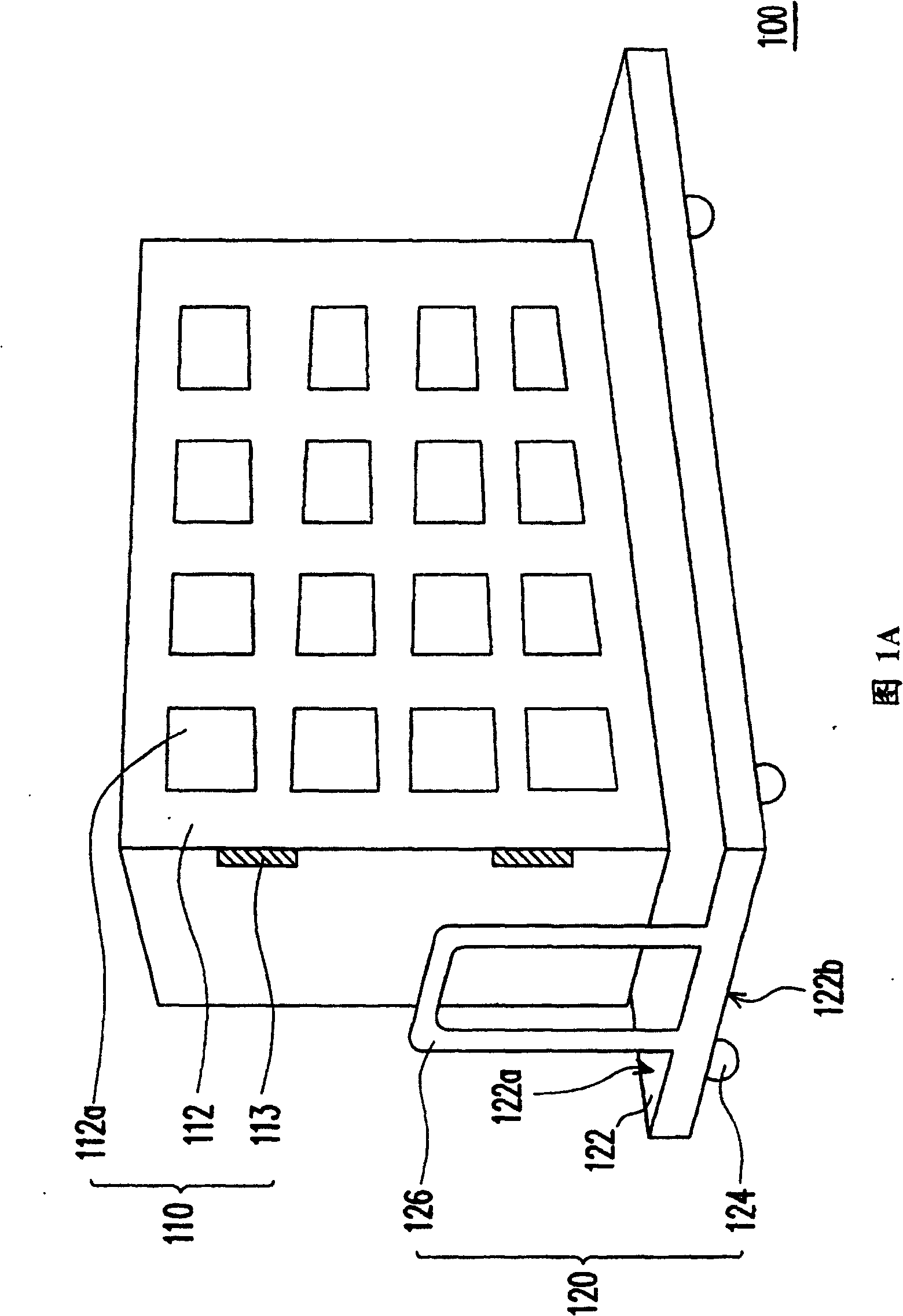
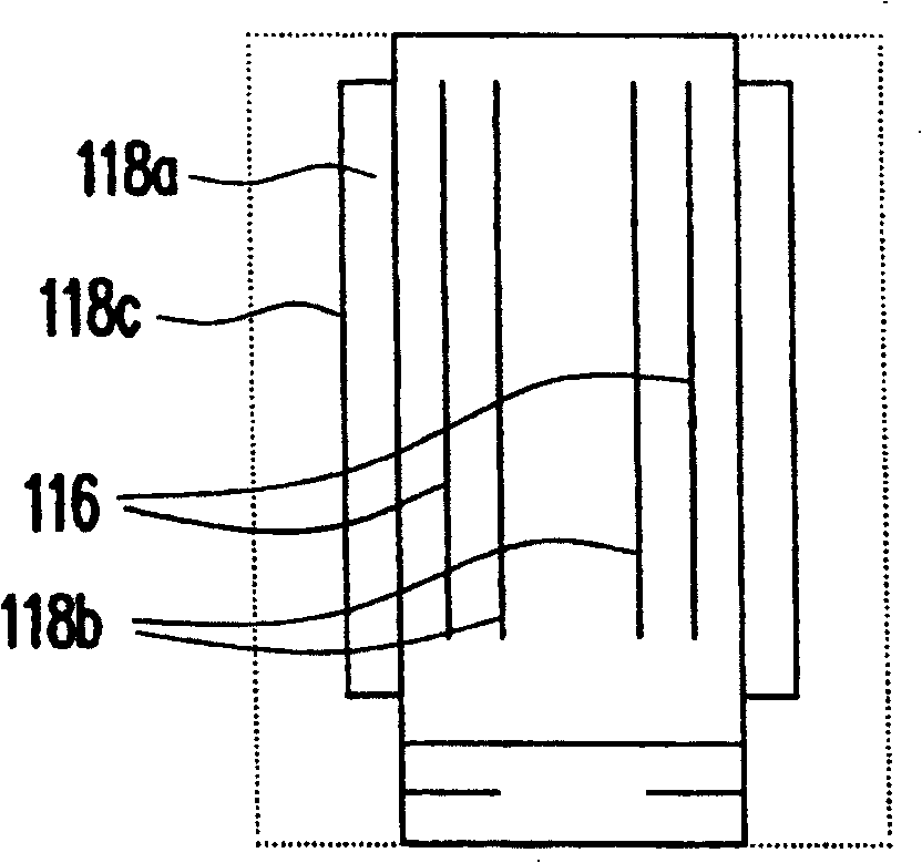
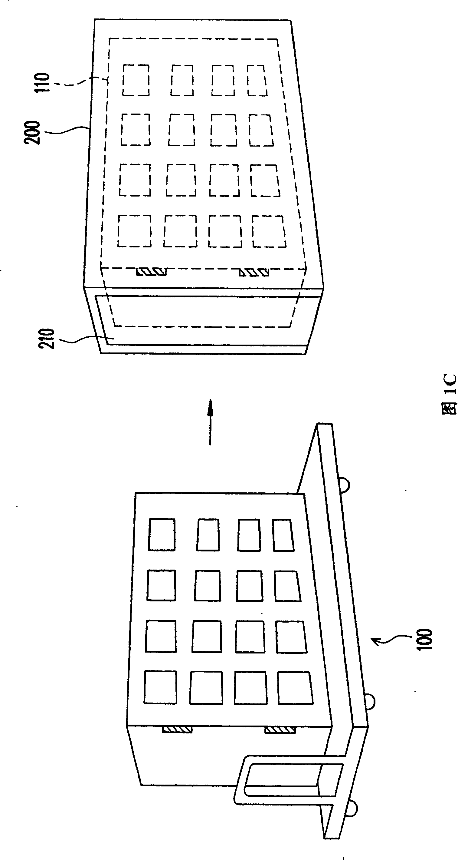
[0033] FIG. 1A is a perspective view of a test rack device for a display panel according to a preferred embodiment of the present invention, Figure 1B It is a top view of a test rack device in a preferred embodiment of the present invention, and FIG. 1C is a schematic diagram of a high-temperature aging test device of the present invention. Also refer to Figure 1A, Figure 1B And Fig. 1C, this test shelf device 100 comprises shelf member 110 and movable base 120, wherein shelf member 110 has side panel 112, and a plurality of test units 112a are arranged on side panel 112, and each test unit 112a It can be connected to a test panel, and a driving circuit (not shown) and a lamp 116 are provided on the shelf member 110 . In addition, the movable base 120 is used to support the shelf member 110, which for example includes a bottom plate 122, a plurality of sliding wheels 124 and a handle 126 that allows the tester to move the base 120, wherein the bottom plate 122 has an upper su...


PUM


Abstract

The testing device for high-temperature ageing of display comprises: a heat furnace member to provide a testing temperature, a frame member with a drive circuit and a lamp and a side board arranged a plurality of testing units with every one connected to a testing board, and a movable base to support the frame and permit it in or out from the furnace..

Description

technical field [0001] The invention relates to a device, and in particular to a high-temperature aging test device for a display panel (Display Panel). Background technique [0002] Since the invention of the first black-and-white television with a cathode ray tube (Cathode Ray Tube, CRT) working mode, display technology has been evolving at a rapid pace. At present, the display technology has been mature and popular, such as mobile phones, language translators, digital cameras, digital video cameras, TVs, personal digital assistants (PDA, personal digital assistant), notebook computers and even desktop displays have their scope of application . [0003] As the current display panel industry is developing towards automatic technology, but the product process design and testing equipment are not fully matched, there are still many problems to be improved in the known display panel testing devices and methods. [0004] Generally speaking, the design of commercially availabl...

Claims


Application Information

Patent Timeline
Patent Type & Authority Patents(China)
IPC IPC(8): G01R31/28G01R31/00
Inventor 林旻保
Owner TPO DISPLAY
Why Eureka
Try Eureka