Illumination device for backlighting an image reproduction device

A technology for lighting devices and reproduction devices, which is applied to lighting devices, light guides of lighting systems, instruments, etc., can solve the problems of difficulty in manufacturing and cannot realize the serial connection of a single light-emitting diode, and achieve the effects of long life, good heat conduction and high efficiency

Inactive Publication Date: 2008-08-20
OSRAM OPTO SEMICONDUCTORS GMBH & CO OHG
View PDF7 Cites 0 Cited by
  • Summary
  • Abstract
  • Description
  • Claims
  • Application Information

AI Technical Summary

Problems solved by technology

However, such a device is difficult to fabricate, especially the series connection of individual LEDs cannot be realized

Method used


Image

  • Illumination device for backlighting an image reproduction device
  • Illumination device for backlighting an image reproduction device
  • Illumination device for backlighting an image reproduction device

Examples


Embodiment Construction

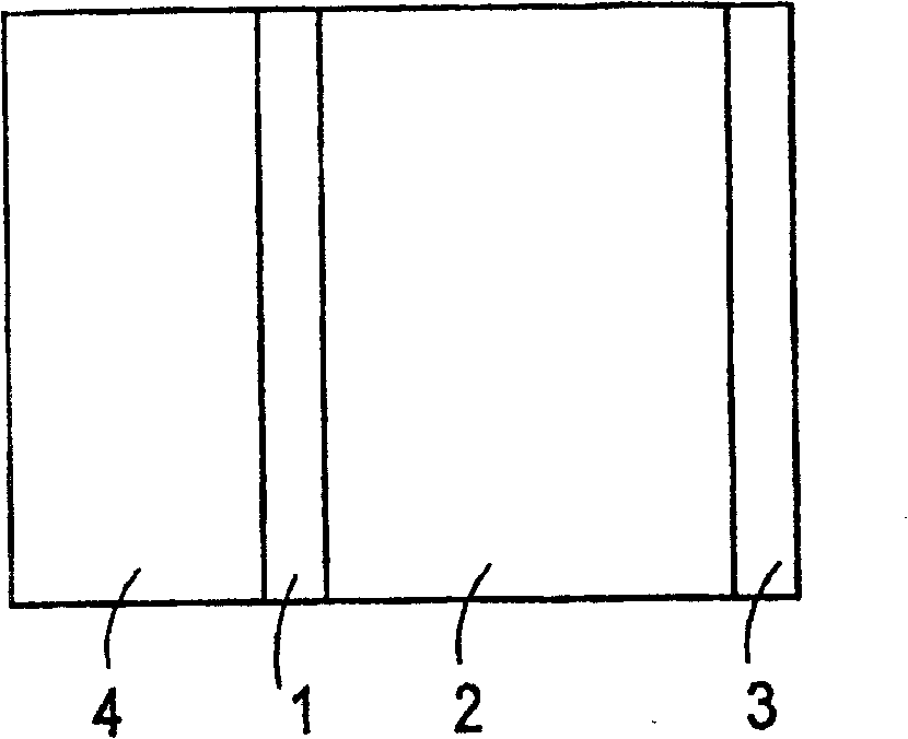
[0030] figure 1 A device is schematically shown with a light source 1 and a display 3, wherein an optical arrangement is arranged between the light source 1 and the display 3 for focusing the light emitted from the light source 1 in the sense of a uniform distribution onto the side of the display 3 On the surface. The distance between the light source and the display is a few centimeters. A cooler 4 for heat conduction is located on the back of the light source 1 .

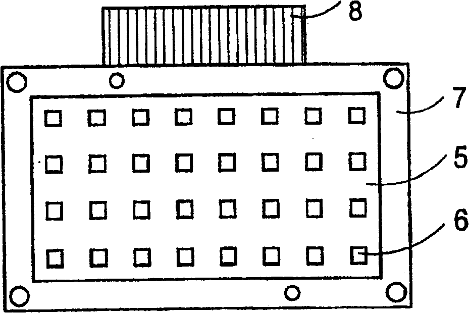
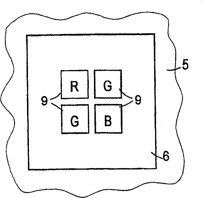
[0031] figure 2 Shown is a top view of a light source 1 with a white plastic frame comprising, in the illustrated embodiment, 8×4 holes in which the light spots 6 are located. The size of the plastic frame 5 is equivalent to the visible area of ​​the display. The plastic frame 5 and the light spot 6 rest on an aluminum plate 7 for fixing and heat conduction. Conductors in the form of flat cables 8 for connecting the light-emitting diodes to the power supply exit from the side.

[0032] image 3 An enlarged...


PUM


Abstract

An illumination device for backlighting an image reproduction device containing light valves, the illumination device including a plurality of luminous spots arranged in grid format on a flat thermally conductive carrier. Each luminous spot having a plurality of light emitting diodes electrically insulated from one another, and a submount exhibiting good thermal conductivity and being connected to the carrier.

Description

technical field [0001] The invention relates to a lighting device for backlighting an image reproduction device including light valves, in which light spots each formed from a plurality of light-emitting diodes are arranged in the form of a grid. Background technique [0002] Image reproduction devices with light valves, in particular liquid crystal displays, require sufficiently bright and uniform backlighting. This is achieved with fluorescent tubes in the case of relatively large displays, such as computer screens. However, in the case of applications where very high brightness is required, the known lighting devices are not sufficient. For example, a very high brightness is required for so-called head-up displays (head-up displays) in motor vehicles, since a mirror image of the display must still be visible even when the ambient light is high. [0003] GB 2361581A shows a device with light emitting diodes arranged in cavities in a thermally conductive substrate. A plu...

Claims


Application Information

Patent Timeline
Patent Type & Authority Patents(China)
IPC IPC(8): G02F1/13357H01L33/00H05B33/08G02F1/1335H01L25/075H01L33/60H05B44/00
CPCH01L25/0753H01L2224/8592H05B33/0821H01L33/60G02F1/133603H01L2224/48472H01L2224/48091H05B33/0803H01L2924/00014H01L2924/00G02F1/1335G02B6/0001H05B45/00H05B45/40
Inventor H·诺尔R·迈尔P·克罗莫蒂斯G·博纳
Owner OSRAM OPTO SEMICONDUCTORS GMBH & CO OHG
Why Eureka
Try Eureka