Differential input stage for electronic equipment, comprising means for reducing interference caused by a voltage or current in common mode

A technology of differential input, electronic equipment, applied in the direction of current supply device, differential amplifier, DC-coupled DC amplifier, etc., can solve the problems of phase delay, affecting the effect of feedback, etc.

Inactive Publication Date: 2008-08-20
ALCATEL LUCENT SAS
View PDF3 Cites 0 Cited by
  • Summary
  • Abstract
  • Description
  • Claims
  • Application Information

AI Technical Summary

Problems solved by technology

In practice, the inverter that inverts this voltage introduce

Method used


Image

  • Differential input stage for electronic equipment, comprising means for reducing interference caused by a voltage or current in common mode
  • Differential input stage for electronic equipment, comprising means for reducing interference caused by a voltage or current in common mode
  • Differential input stage for electronic equipment, comprising means for reducing interference caused by a voltage or current in common mode

Examples


Embodiment Construction

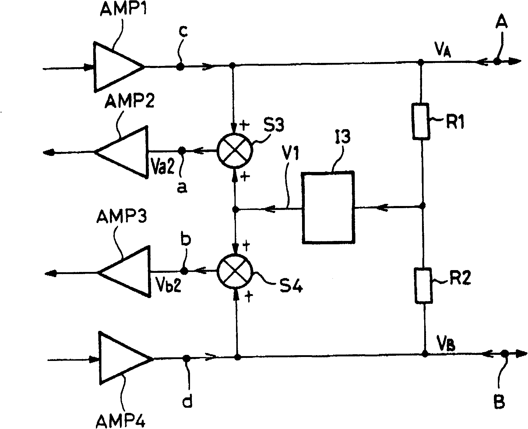
[0021] figure 1 The given embodiment is for the user card input-output stage. it includes:

[0022] Two circuit connections A and B, connectable to subscriber lines;

[0023] Two output circuit connectors a and b are connected to the input ends of the amplifiers AMP2 and AMP3 on the user card;

[0024] Two input circuit connectors c and d, connected to the output terminals of the respective amplifiers AMP1 and AMP4 on the user card, and respectively connected to the input-output circuit connectors A and B;

[0025] A bridge comprising two equal impedance resistors R1 and R2 between circuit connections A and B;

[0026] Inverter I3, the input of which is connected to the midpoint of bridge R1R2;

[0027] an adder S3 having one input connected to circuit connections c and A, one input connected to the output of inverter I3, and the output connected to output circuit connection a; and

[0028] The adder S4 has one input connected to the circuit connections d and B, one input...


PUM


Abstract

According to the invention, means for reducing the interference caused by a voltage or a current in common mode, comprise adders (S3; S4) in each path for adding a first counter-reaction voltage (VI) to the voltage of the relevant path, a bridge (R1, R2) and an inverter (I3) for provision of said first counter-reaction voltage which is equal to half the sum of the voltages (VA; VB), respectively supplied to the inputs (A; B), with an opposing sign. According to the invention, the effect of a delay introduced by the inverter (I3) may be reduced, whereby said stage further comprises means (S5; S6) for adding in addition to the input voltage for each path, a second counter-reaction voltage (Val; Vbl), and means (R1, R2,; I1, S1; I2, S2) for provision of a second counter-reaction voltage (Val; Vbl) which is a function of the input voltage (VA; VB) at the input corresponding to said path, with an opposing sign and with a delay identical to that generated by the inverter (I3).

Description

technical field [0001] The invention relates to a differential input stage of an electronic device comprising means for reducing disturbances caused by common mode voltages or currents applied to the two inputs of the stage. More particularly, the present invention relates to subscriber cards and subscriber terminals used in telephone exchanges. The subscriber card is connected to the subscriber terminal by a line comprising at least two conductors for carrying voice or data signals in both directions, and a DC voltage to provide a remote power feed to the terminal. These signals are transmitted in differential mode, that is, in the form of a voltage difference between two wires. Background technique [0002] The circuitry of the subscriber card or subscriber terminal is susceptible to interference from undesired common-mode signals. This common mode interference appears in the form of voltages and equivalent currents on the two conductors of the subscriber line. These vo...

Claims


Application Information

Patent Timeline
IPC IPC(8): H03F3/45H04M19/00
CPCH03F3/45941
Inventor 让-皮埃尔·布齐迪
Owner ALCATEL LUCENT SAS
Why Eureka
Try Eureka