Data transfer device, data transfer system and data transfer method

一种数据传送、数据量的技术,应用在电数字数据处理、数据处理的输入/输出过程、仪器等方向,能够解决有效数据传送速度低、数据错乱等问题

Inactive Publication Date: 2008-09-10
SOCIONEXT INC
View PDF1 Cites 0 Cited by
  • Summary
  • Abstract
  • Description
  • Claims
  • Application Information

AI Technical Summary

Problems solved by technology

[0007] Here, for the above-mentioned data disorder, improving the transmission line and setting the signal processing time are general solutions. Therefore, it has not been considered that the low effective data transmission speed will become a problem before.

Method used


Image

  • Data transfer device, data transfer system and data transfer method
  • Data transfer device, data transfer system and data transfer method
  • Data transfer device, data transfer system and data transfer method

Examples


Embodiment 1

[0041] Next, as Embodiment 1 of the present invention, a data transfer system in which an optical disc device of the data transfer device of the present invention is connected to a host computer will be described with reference to the drawings. Here, for the connection and data transfer between the host computer and the optical disc device, for example, IDE bus and UitraDMA transfer methods are used, and the maximum data transfer speed that can be transmitted by the host computer and the optical disc device is 66.7MBytes / sec (transfer mode 4 ).

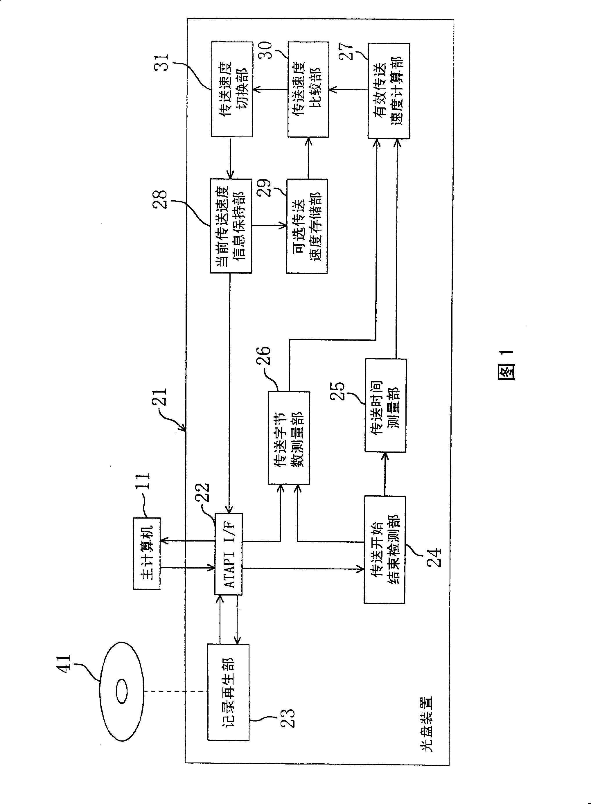
[0042] FIG. 1 is a block diagram showing a main part of an optical disk drive 21 connected to a host computer 11. As shown in FIG. In the configuration of FIG. 1 , ATAPI I / F 22 (sending means, receiving means) is a means for sending and receiving control signals and transferring data to and from the host computer 11 . The data transfer is specifically performed by outputting a strobe signal at a time synchronized with the strobe sign...

Embodiment 2

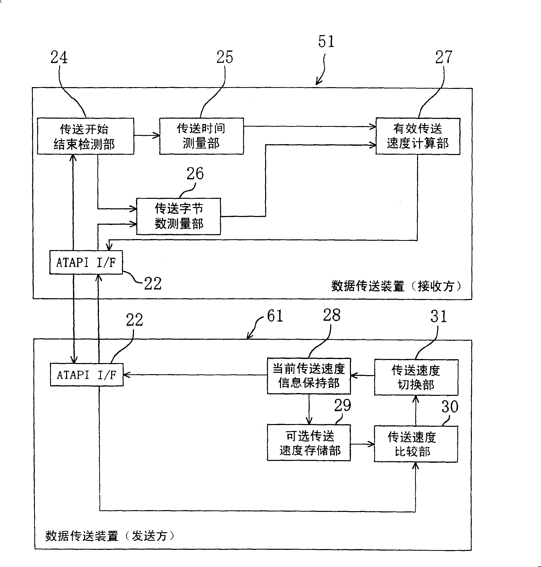
[0066] The data transmission device on the receiving side detects the effective data transmission speed, and according to this speed, the data transmission device on the sending side switches the transmission speed. Next, taking the data transmission system having such a configuration as an example, based on image 3 Be explained. In addition, in this embodiment, the components having the same functions as those in the first embodiment are assigned the same symbols and their descriptions are omitted. In addition, in image 3 In the figure, the recording / reproducing unit 23 is omitted for convenience.

[0067] In the data transmission system of the second embodiment, the data transmission device 51 on the receiving side is provided with a transmission start and end detection unit 24, a transmission time measurement unit 25, a transmission byte count measurement unit 26, and an effective transmission speed calculation unit 27, and Same as in Embodiment 1, the effective data tran...


PUM


Abstract

This invention provides a data transfer device, data transfer system, and data transfer method.a transfer start / end detecting section detects timing at which a DMARQ signal becomes an H level or an L level. A transfer time-measuring section measures a transfer time during which data transfer is actually performed within a period in which a predetermined number of data blocks are transferred. A transfer byte count-measuring section measures a transferred byte count of data that have successfully been transferred. An effective data transfer rate-computing section computes an effective data transfer rate by dividing the transferred byte count by the transfer time. A transfer rate-comparing section compares the effective data transfer rate with a transfer rate that is one step slower than a current transfer rate output from a selectable transfer rate-storing section. If the former is slower, a transfer rate-switching section switches to the transfer rate that is one step slower. A large decrease in the effective data transfer rate caused by data corruption is prevented.

Description

technical field [0001] The present invention belongs to technologies related to, for example, data transfer between a host computer and an optical disc device, etc., and relates to a data transfer device constituting the above-mentioned host computer, optical disc device, etc. A data transmission system and a data transmission method for performing data transmission between them. Background technique [0002] So far, for example, IDE bus (ATA / ATAPI interface standard) has been widely used in connection with the host computer as the host computer and optical disk devices such as DVD-ROM drives and CD-R / RW drives as peripheral devices, and UItra is used as the transmission method. DMA. In this UItra DMA standard, the conventional transfer modes 0 to 2 are added in accordance with the data transfer rate, and transfer modes 3 and 4 are added, enabling data transfer at a transfer rate of 16.7 to 66.7 Mbytes / sec. In addition, the standardization of transmission modes 5 and 6 (10...

Claims


Application Information

Patent Timeline
Patent Type & Authority Patents(China)
IPC IPC(8): G06F13/14G06F13/28G06F3/00G06F3/06G06F13/00G06F13/42
CPCH04N21/42646H04N21/442H04N21/4425H04N21/4424
Inventor 铃木达夫初濑川明广
Owner SOCIONEXT INC
Why Eureka
Try Eureka