
Knitting machine

A knitting machine and knitting needle technology, applied in the field of knitting machines, can solve the problems of damage to the quality of knitting products, high production costs, damaged parts, etc., achieve fast and easy assembly and replacement, reduce manufacturing precision requirements, and reduce production costs Effect

Inactive Publication Date: 2008-10-01
AMTEC CO LTD
View PDF13 Cites 0 Cited by
  • Summary
  • Abstract
  • Description
  • Claims
  • Application Information

AI Technical Summary

Problems solved by technology

[0008] The disadvantage of this arrangement is that it is expensive to produce due to the high demands on precision, and that it is screwed on the fixing mechanism to be able to release it requires the needle triangle sector, which is not possible without a corresponding tool Screws, moreover, in the case of insufficient fixation of the screws may occur, or on the contrary, due to the well-known disadvantage of this technical solution, that is, excessive fixation of the screws, damage to the components may occur
Another disadvantage of the technical solution of US Patent No. 3696641 is that the production tolerances of the height of the needle cam segments in the direction along the fixing mechanism (the needle cam segments are placed on top of each other by their ends) accumulate, This requires extremely high production precision, or it impairs the quality of the weave due to the unevenness of the stitches in the individual tracks

Method used


Image

  • Knitting machine
  • Knitting machine
  • Knitting machine

Examples


Embodiment Construction

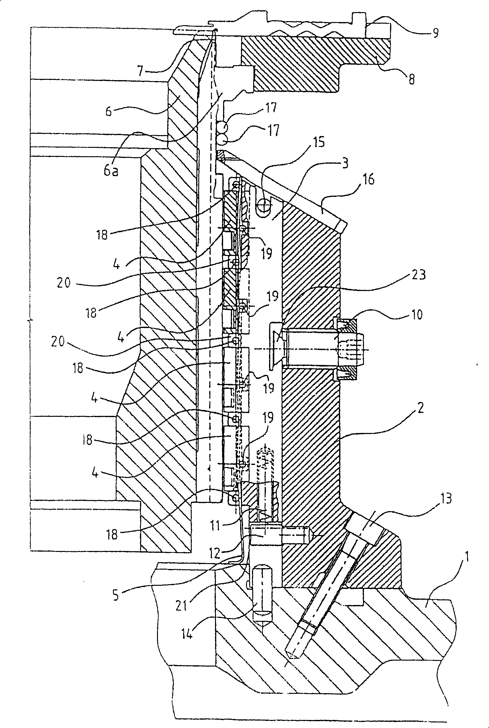
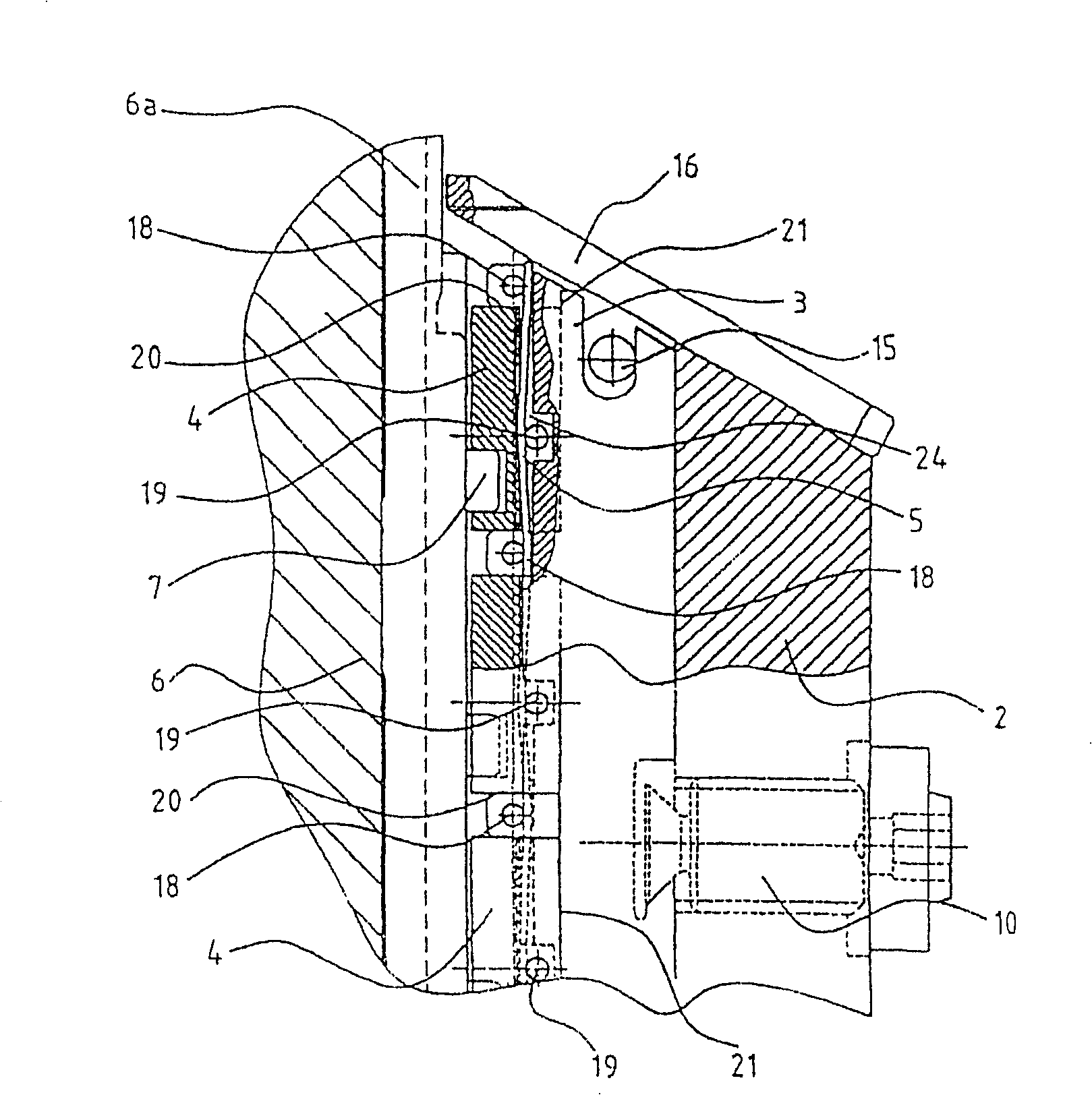
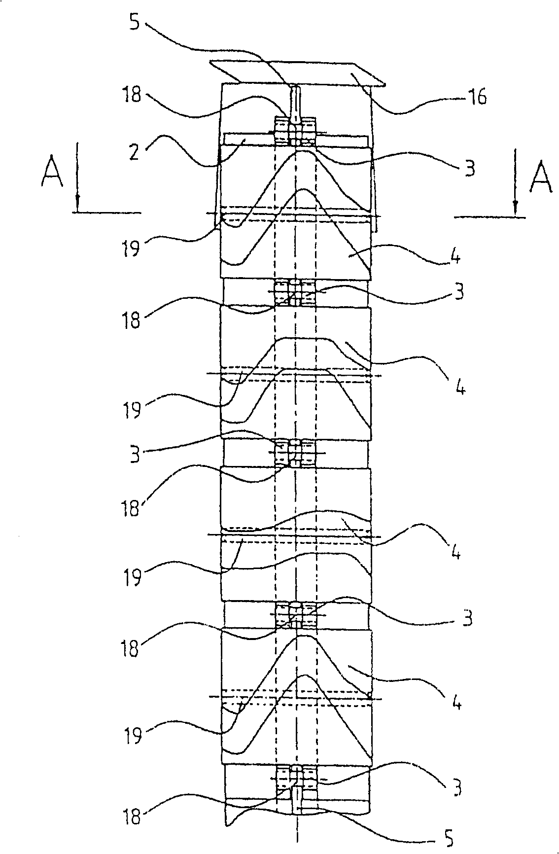
[0038] The present invention will be illustrated with a circular knitting machine with a single needle plate, the parts that are more important to the present invention are shown in section in figure 1 , and in the area of ​​a circular cylindrical needle plate 6 is shown as a needle cam system, and shown in detail necessary to illustrate the principles of the invention. The details of the fixing and driving of the needle plate 6 and the sinker ring 8, as well as the usual arrangement of the needle cams for controlling the knitting mechanism - the needles 7 and the sinkers 9 - are well known to those skilled in the art, And therefore its illustration has been omitted for simplification of description.

[0039] This knitting machine carries a knitting needle triangular fan-shaped plate carriage 1, and at least one fixed part 2 of this knitting needle triangular carriage is fixed on the carriage 1 with screws 13, wherein in the needle groove with the needle plate 6 6a The movabl...


PUM


Abstract

The invention relates to a knitting machine with at least one bed with ribs between which knitting means are situated free to move and coupled with needle cams serving to control them, each of them consisting of at least one needle cam section (4), with needle cams arranged on at least one needle cam carrier arranged at a fixed distance from the bed on at least one carrier (1) of needle cam blocks and fitted with attachment and positioning means for fixing the needle cam sections (4) and for keeping the position of the needle cam sections in relation to the stationary and / or movable part (2, 3) of the needle cam carrier, said attachment and positioning means permitting in the dismantled state of the needle cam carrier to mount and / or to remove the needle cam sections (4) from the front side of the needle cam carrier. The attachment means consists of at least one shifting attachment means (5) arranged substantially parallel to the front side (21) of the needle cam carrier by means of which at least one needle cam section (4) is held on the needle cam carrier and of at least one positioning means arranged substantially normal to the front side (21) of the needle cam carrier by means of which the needle cam sections (4) are held in required position in relation to the needle cam carrier.

Description

technical field [0001] The present invention relates to a knitting machine. Background of the invention [0002] The knitting machine can be equipped with various knitting needle cam devices, and each knitting needle cam device can be composed of one or more than one knitting needle cam fan-shaped plates. In a technical solution well known to experts and often used, the needle cam sector plate is fixedly or even exchangeably mounted on the needle cam carriage, and on the front of the needle cam carriage is formed a needle cam for the knitting mechanism. The closed groove-shaped path of the heel, or the triangular fan-shaped plate of the knitting needle also forms the triangular path of the knitting needle controlled by the action of the knitting mechanism. A comprehensive technical solution is also known. The fixing mechanism of the needle cam plate generally comprises an opening in the front face of the needle cam carriage fitted with yarn, and passes through the opening ...

Claims


Application Information

Patent Timeline
Patent Type & Authority Patents(China)
IPC IPC(8): D04B15/32
CPCD04B15/32
Inventor 费朗齐歇克·布什库拉
Owner AMTEC CO LTD
Learn More