

Zero commuter station structure of bus and zero transferring fast public traffic system
A zero-transfer, point-structure technology, applied to roads, roads, buildings, etc., can solve problems such as road traffic congestion, unsuitability, and time-consuming
- Summary
- Abstract
- Description
- Claims
- Application Information
AI Technical Summary
Problems solved by technology
Method used
Image

Examples
Embodiment Construction
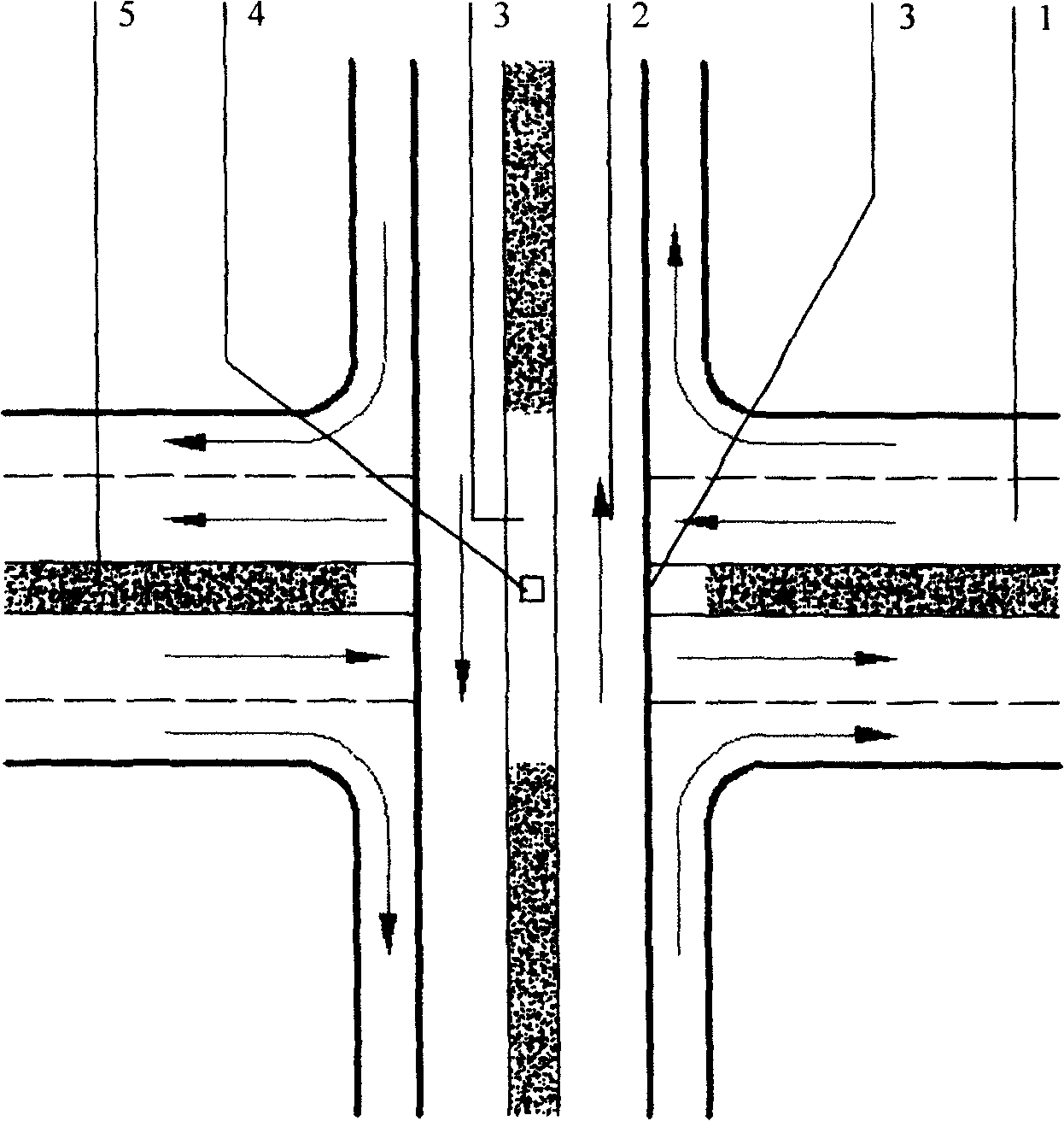
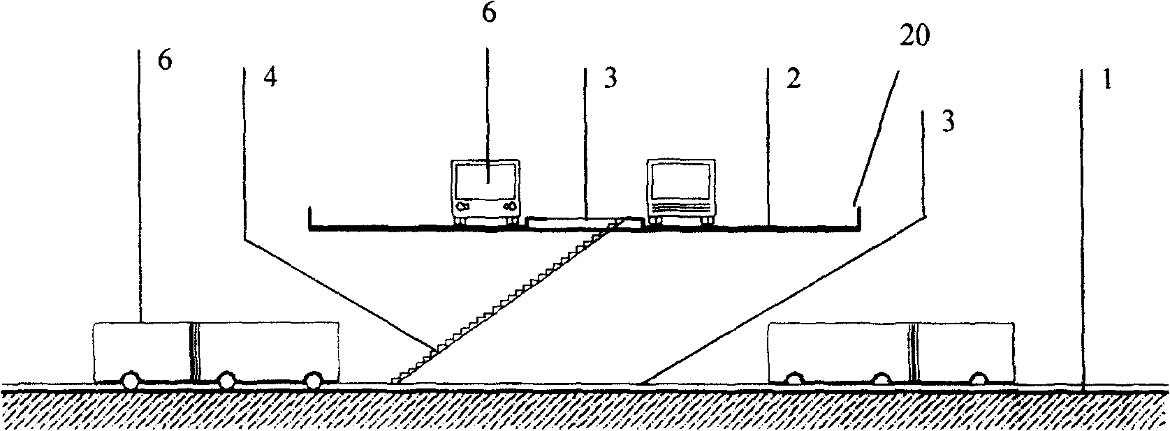
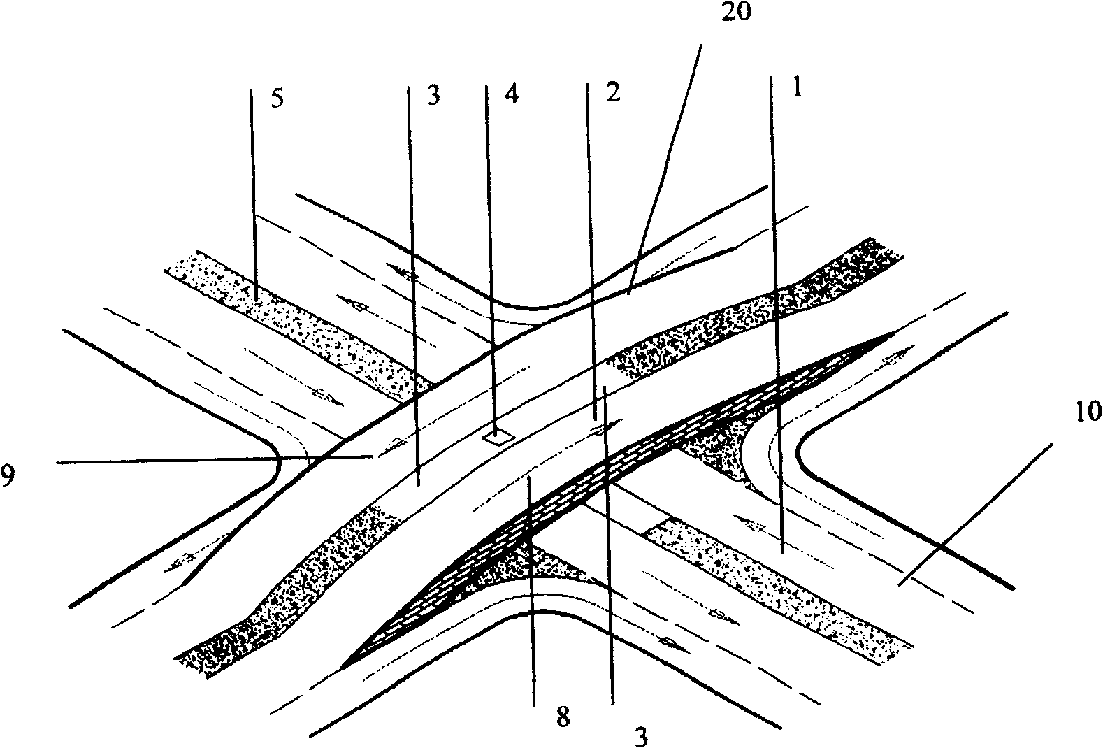
[0023] See attached Figure 1-3 , a zero-transfer bus site structure of the present invention, comprising a bus platform 3, the bus platform 3 is arranged at the intersection of two roads, the lower motor vehicle lane 1 and the upper motor vehicle road 2, and the intersection is set For the upper and lower two-layer roads 20,10 that intersect each other, the public transport vehicle 6 of the upper and lower two-layer lines stops on the platform 3 of the upper and lower two-layer roads 20,10 respectively, and the upper and lower two-layer roads 20,10 Pedestrian stairs or escalators 4 for passengers to pass through, connecting the upper and lower platforms are arranged between them. Passengers can realize transfer by going up or down through the pedestrian stairs or escalator 4 . In this way, there is no need to walk long distances when transferring, and zero transfers are realized.
[0024] The upper and lower two-layer road 20,10 structure of this intersection can be image...
PUM
 Abstract
Description
Claims
Application Information