Optical fiber display

A technology of display and optical fiber, which is applied in the field of optical fiber display, can solve the problem of high cost of optical fiber display, and achieve the effect of reducing costs

Inactive Publication Date: 2008-10-15
HONG FU JIN PRECISION IND (SHENZHEN) CO LTD +1
View PDF8 Cites 0 Cited by
  • Summary
  • Abstract
  • Description
  • Claims
  • Application Information

AI Technical Summary

Problems solved by technology

[0004] In order to solve the problem of high cost of fiber optic displays in the prior art, the present invention provides a low cost fiber optic display

Method used


Image

  • Optical fiber display
  • Optical fiber display
  • Optical fiber display

Examples


Embodiment Construction

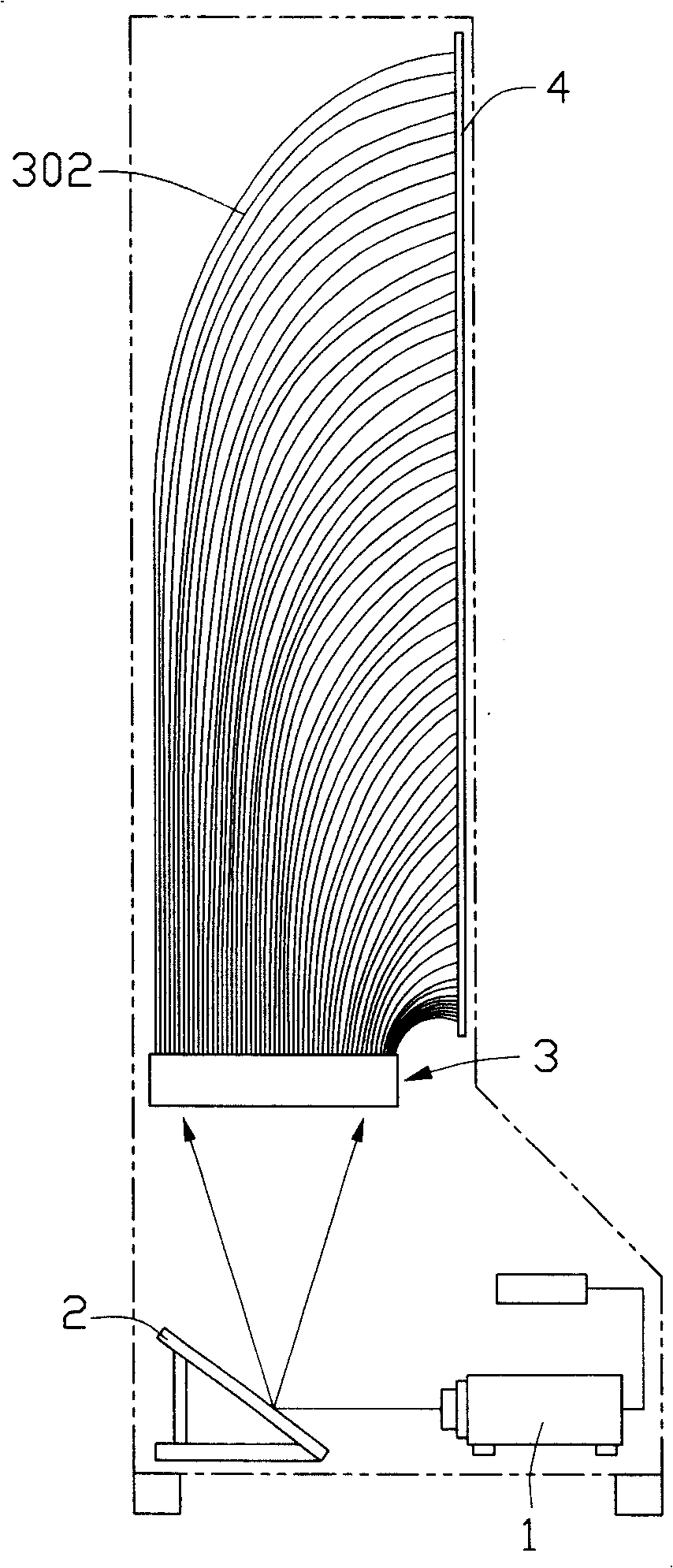
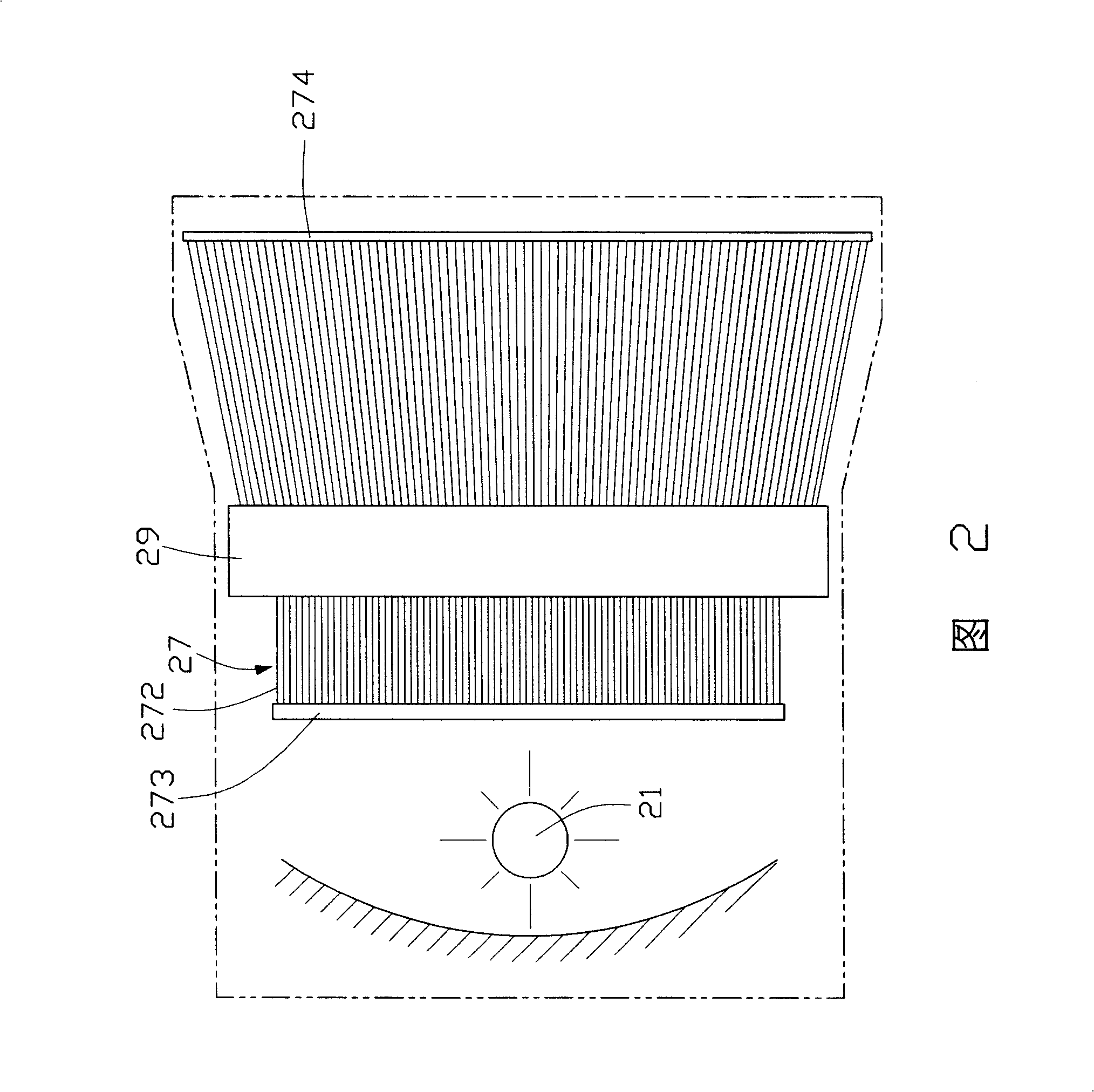
[0018] Please refer to FIG. 2 , which is a schematic plan view of the first embodiment of the fiber optic display of the present invention. This fiber optic display includes a light source 21, an optical fiber bundle 27 and a brightness adjusting device 29, wherein the optical fiber bundle 27 is made up of a plurality of optical fibers 272, wherein one end of the plurality of optical fibers 272 forms a light-incoming end 273 for receiving The other end of the light emitted by the light source 21 constitutes a display end 274 .

[0019] see image 3 and Figure 4 , the brightness adjustment device 29 is composed of a plurality of optical switches corresponding to the plurality of optical fibers 272 one by one, the optical switch includes a filter 32, the angle between the plane of the filter 32 and the optical fiber 272 is θ, wherein The filter 32 can be rotated after being controlled by a microelectromechanical device, such as Figure 4 As shown, the angle θ between the pla...


PUM


Abstract

The invention relates to an optical fiber display, which comprises a light source, an optical fiber beam and a brightness adjuster, wherein the optical fiber beam is formed by a lot of optical fibers; one end of the optical fibers placement are formed to a light inlet end; the other end is formed to a display end; the brightness adjuster comprises a plurality of light switches which are separately corresponding to the plurality of optical fibers and are positioned between the light inlet end the display end. The optical fiber display can also comprise a color filter, a light coupled component, a visible light band filter and a diffusion sheet to achieve the color display.

Description

【Technical field】 [0001] The invention relates to a display, in particular to an optical fiber display. 【Background technique】 [0002] In recent decades, except for some small and medium-sized monitors and notebook computer monitors, it can be said that they are all Cathode Ray Tube (CRT) monitors. However, due to the popularization of network broadband and changes in digital signal transmission methods , various new display technologies emerged as the times require. Currently, the flat panel displays of the new generation display technology mainly include Liquid Crystal Display (LCD), Plasma Display Panel (PDP), projection display, and Organic Light Emitting Display (OLED). [0003] Mainland China Patent No. 97243700 published on June 23, 1999 discloses a fiber optic display in the prior art. The fiber optic display uses optical fibers in pixels to overcome the loss problem in the image transmission process and realize the enlargement of the display. Such as figure 1 As...

Claims


Application Information

Patent Timeline
Patent Type & Authority Patents(China)
IPC IPC(8): G02B6/06G02B27/01G02B27/18
Inventor 李俊佑蔡明江江宗韦
Owner HONG FU JIN PRECISION IND (SHENZHEN) CO LTD
Why Eureka
Try Eureka