
Magnet polar plate of magnetic resonance

A magnetic resonance imaging and polar plate technology, which is applied in medical science, sensors, diagnostic recording/measurement, etc., can solve problems such as large eddy currents

Inactive Publication Date: 2008-11-12
INST OF ELECTRICAL ENG CHINESE ACAD OF SCI
View PDF7 Cites 0 Cited by
  • Summary
  • Abstract
  • Description
  • Claims
  • Application Information

AI Technical Summary

Problems solved by technology

[0011] The purpose of the present invention is to solve the problem that the polar plate of the magnetic resonance imaging magnet in the prior art produces a large eddy current when the axial gradient coil is working, and further improve the imaging level of the magnetic resonance imaging system. For this reason, the present invention proposes a Magnetic resonance imaging magnet plate with new structure

Method used

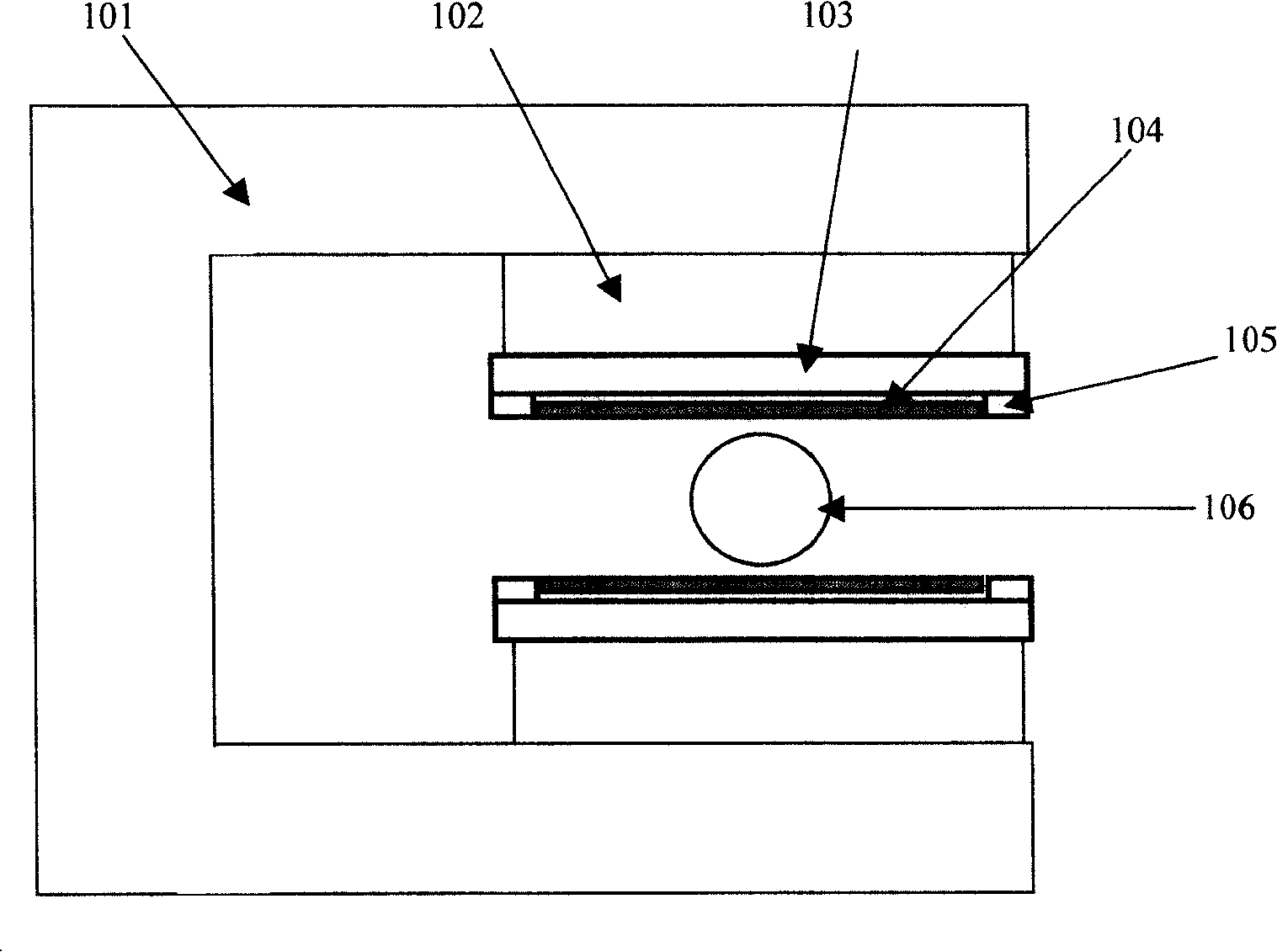
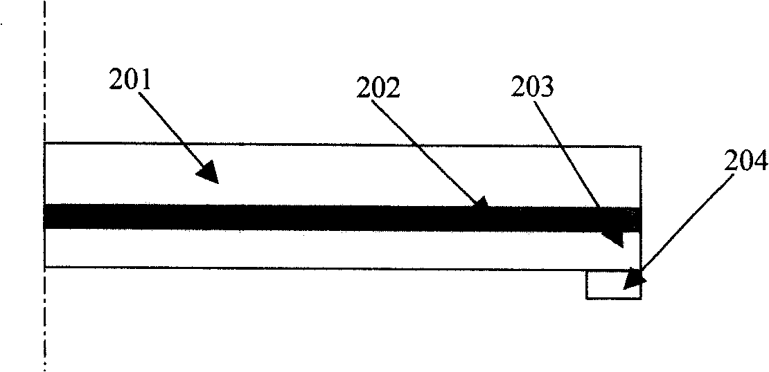
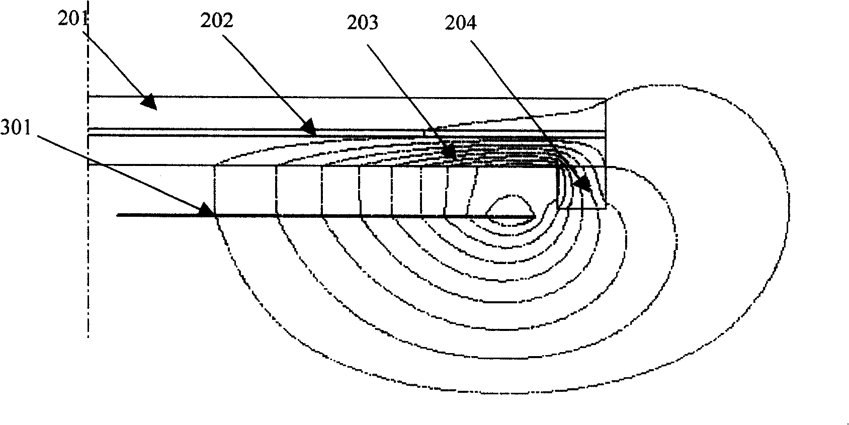

Image

  • Magnet polar plate of magnetic resonance
  • Magnet polar plate of magnetic resonance
  • Magnet polar plate of magnetic resonance

Examples


Embodiment Construction

[0026] The present invention will be further described below in conjunction with the accompanying drawings and specific embodiments.

[0027] Figure 4 Shown is the basic structural principle of the present invention. The pole plates are arranged in the direction from the magnetic pole head to the imaging space, and are composed of a pole plate head 401, insulating layers 402, 403, a dredging layer 405, and a guide ring 404. At the same time, there is a shim ring on the side close to the imaging space 406. Wherein, the guide ring 404 is a ring attached around the side of the plate head 401 . The pole plate head 401 is made of both magnetic and conductive materials. In order to prevent the magnetic field lines from entering the pole plate head 401, a layer of non-magnetic and non-conductive insulating layers 402 and 403 are attached to the bottom and sides of the pole plate machine head 401, and then a magnetically conductive and non-conductive insulating layer of sufficient...


PUM


Abstract

A magnetic plate electrode of magnetic resonance imaging (MRI) system for improving the image quality greatly is composed of an electrode end for generating a uniform magnetic field, an eddy isolating insulation layer, a conductive layer, a guide ring for leading the direction of magnetic flux, and an external field-uniforming ring.

Description

technical field [0001] The present invention relates to Magnetic Resonance Imaging (MRI) systems, and in particular to pole plates for Magnetic Resonance Imaging magnets. Background technique [0002] When the magnetic resonance imaging system works, the human body is placed in a strong static magnetic field, and the atomic nuclei in some areas of the human body are excited by sending radio frequency pulses to the human body. After the radio frequency field is removed, these excited nuclei radiate radio frequency signals, which are received by the antenna. When a gradient magnetic field is added in this process, the spatial distribution information of the human body can be obtained through radio frequency signals, thereby reconstructing a two-dimensional or three-dimensional image of the human body. [0003] The gradient magnetic field is generated by the gradient coil, which is installed close to the polar plate, and pulse currents with different sizes and widths are appli...

Claims


Application Information

Patent Timeline
Patent Type & Authority Patents(China)
IPC IPC(8): A61B5/055
Inventor 杨文晖宋涛王慧贤王铮
Owner INST OF ELECTRICAL ENG CHINESE ACAD OF SCI
Learn More