
Phase-sequence synthetic brake method for preventing multi-branch transformer differentical protection malfunction
A differential protection and transformer technology, applied in emergency protection circuit devices, electrical components, etc., can solve problems such as inability to perform reliable braking, misoperation of transformer differential protection, and inability to eliminate the influence of zero-sequence current
- Summary
- Abstract
- Description
- Claims
- Application Information
AI Technical Summary
Problems solved by technology
Method used
Image

Examples
Embodiment 1
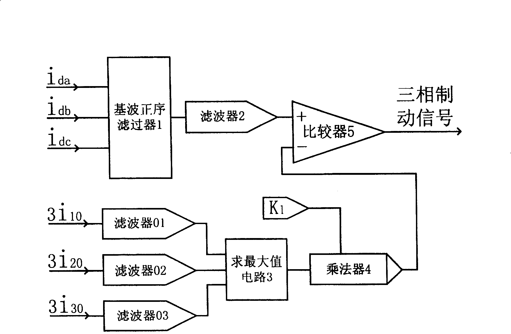
[0011] A phase sequence synthesis braking method for preventing misoperation of differential protection of multi-branch transformers figure 1 A circuit of a positive-sequence synthetic braking device for preventing the misoperation of differential protection of multi-branch transformers is realized. The device consists of filters 01, 02, 03, fundamental positive sequence filter 1, filter 2, and the The value circuit 3, the multiplier 4 and the comparator 5 are constituted, wherein the input terminals of the filters 01, 02 and 03 respectively input the zero-sequence current instantaneous value signal 3i of each neutral point grounding side or branch of the transformer 10 , 3i 20 , 3i 30 , 3i 10 , 3i 20 , 3i 30 After filtering, 3I is obtained 10 , 3I 20 , 3I 30 , the output terminals of the filters 01, 02 and 03 are respectively connected with the input terminal of the maximum value circuit 3, one input terminal of the multiplier 4 is connected to the output terminal of t...
PUM
 Abstract
Description
Claims
Application Information