
Compensation of filters in radio transmitters

A wireless transmitter, transmitter technology, applied in transmitter/receiver shaping network, radio transmission system, baseband system, etc.

Inactive Publication Date: 2008-11-12
ANDREW CORP
View PDF4 Cites 0 Cited by
  • Summary
  • Abstract
  • Description
  • Claims
  • Application Information

AI Technical Summary

Problems solved by technology

[0002] In practice, for example, in order to prevent the base station from interfering with the operation of adjacent equipment, the base station will be subject to certain restrictions on the range of transmission frequencies

Method used


Image

  • Compensation of filters in radio transmitters
  • Compensation of filters in radio transmitters
  • Compensation of filters in radio transmitters

Examples


Embodiment Construction

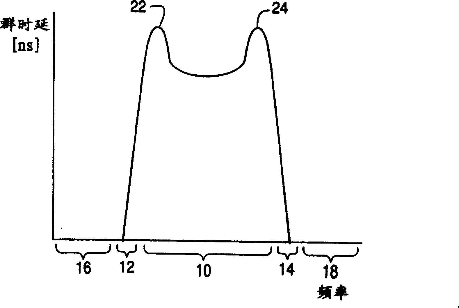
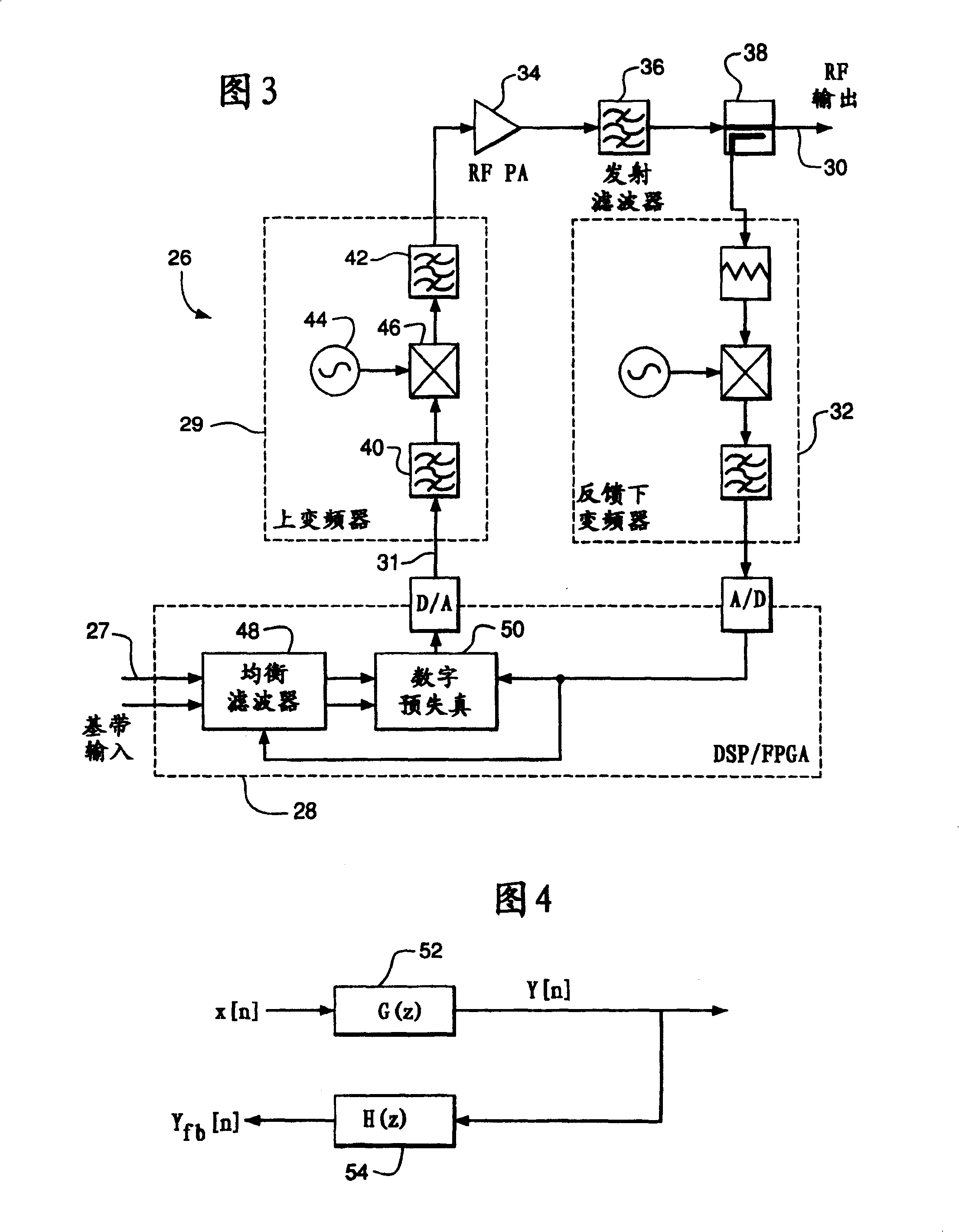
[0013] According to one aspect, the present invention provides a wireless transmitter for transmitting signals in a designated frequency band, including a transmission filter for filtering the signal to be transmitted by the transmitter to suppress the transmission of the signal part located outside the band; and A compensation filter, working in the digital domain, is used to filter the above-mentioned signals located upstream of the transmit filter. The compensation filter is arranged to change the signal to cancel one or more of phase jitter, amplitude jitter, and group delay variation in the passband and / or transition band of the transmit filter.

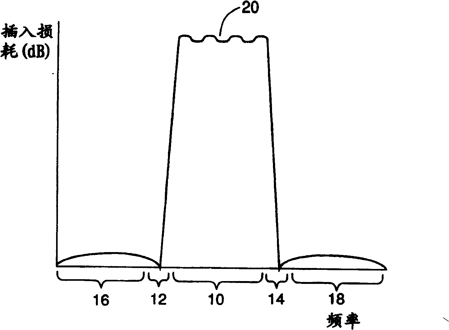
[0014] figure 1 A graph showing the relationship between insertion loss (in dB) and frequency of a typical transmission filter in a base station. The graph shows how the transmit filter attenuates the signal passing through the transmit filter. figure 1 The graph in marks the passband 10 in which the frequency passing the filter ...


PUM


Abstract

A radio transmitter for transmitting signals in a predetermined frequency band has a transmit filter and a compensating filter. The transmit filter filters a signal to be transmitted from the transmitter to suppress the transmission of parts of the signal outside the band. The compensating filter, e.g., operating in the digital domain, filters the signal upstream from the transmit filter, wherein the compensating filter is arranged to alter the signal to counteract at least one of a phase ripple, an amplitude ripple, and a group delay variation of the transmit filter within the band.

Description

Technical field [0001] The present invention relates to a wireless transmitter, which can be used in a base station of a cellular wireless communication network, for example. Background technique [0002] In practice, for example, in order to prevent the base station from interfering with the operation of neighboring devices, the base station will be subject to certain restrictions on the range of transmission frequencies. In order to achieve this restriction, the base station usually includes a transmission filter to suppress any frequency in the radio frequency signal to be transmitted that lies outside the frequency band designated for transmission by the base station. Summary of the invention [0003] The present invention provides a wireless transmitter for transmitting signals in a designated frequency band, including: a transmission filter for filtering the signal to be transmitted from the transmitter to suppress the transmission of the out-of-band part of the signal Com...

Claims


Application Information

Patent Timeline
IPC IPC(8): H04B1/04H04B1/40H04B7/00H04B1/02H04B7/155H04L25/03H04L27/36
CPCH03F1/3247H04L27/368H04L25/03343H04B7/00H04B7/155H04B1/04
Inventor 彼得·B.·吉宁顿
Owner ANDREW CORP
Learn More