Vehicle front end structure

A technology for vehicles, gap structures, applied in the direction of superstructure, vehicle components, superstructure sub-assemblies, etc., can solve problems such as reduced maintainability, difficult to replace front panels and shields, etc.

Inactive Publication Date: 2008-11-19
DENSO CORP
View PDF6 Cites 0 Cited by
  • Summary
  • Abstract
  • Description
  • Claims
  • Application Information

AI Technical Summary

Problems solved by technology

Therefore, it is difficult to replace the front panel and the shroud individually or independently, for example, when the vehicle is involved in a collision and parts are damaged
As a result, easily reduced maintainability

Method used


Image

  • Vehicle front end structure
  • Vehicle front end structure
  • Vehicle front end structure

Examples


no. 1 example

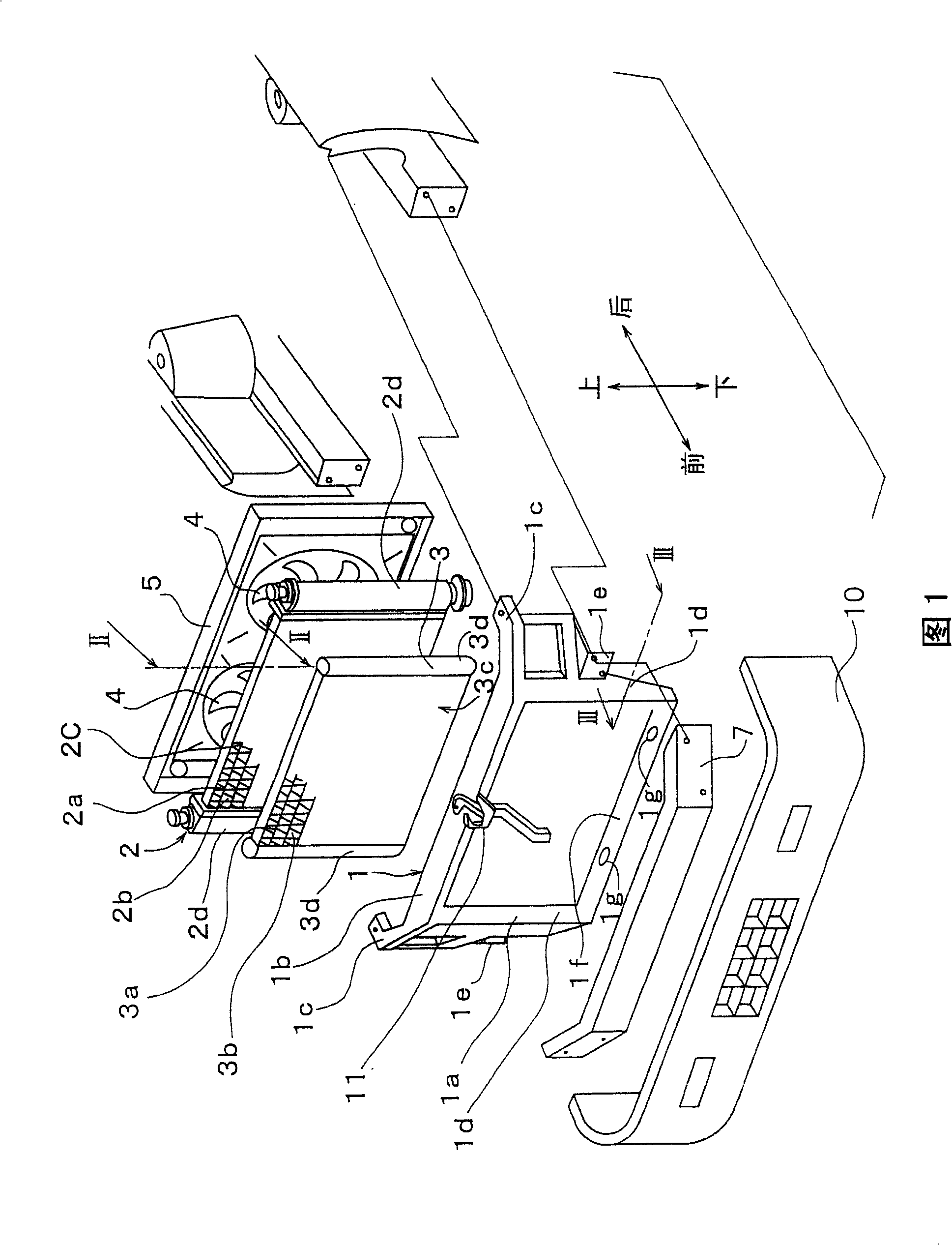
[0016] Referring to FIG. 1 , a front panel 1 is fixed to a vehicle body at a vehicle front end. The front panel 1 extends substantially in the left-right direction of the vehicle (the width direction of the vehicle). The front panel 1 includes a frame portion 1a, a first fixing portion 1c, and a second fixing portion 1e. The frame portion 1a has a substantially rectangular shape. The first fixing portion 1c extends from the longitudinal end portion of the upper beam portion 1b of the frame portion 1a toward the vehicle body side. The second fixing portion 1e is formed on the side column portion 1d of the frame portion 1a.

[0017] Also, a radiator fixing portion 1g for fixing the radiator 2 is formed on the lower beam portion 1f and the upper beam portion 1b of the frame portion 1a. The heat sink 2 is elastically supported by the front panel 1 through an elastic support member (not shown) such as elastically deformable anti-vibration rubber. In this embodiment, the frame p...

no. 2 example

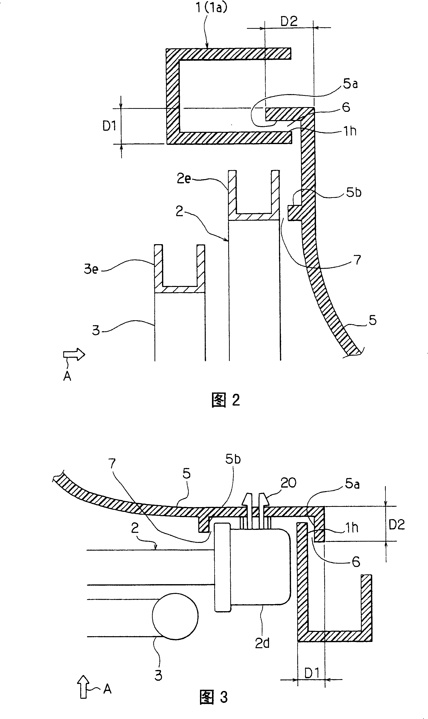
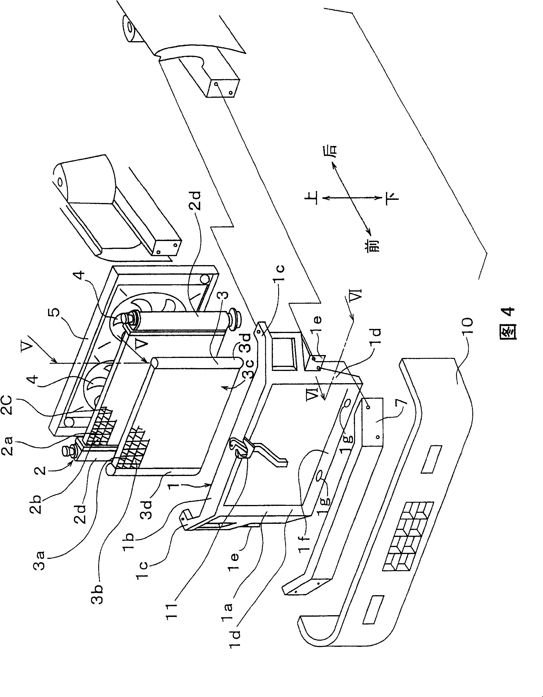
[0034] Referring to FIGS. 4 to 6 , the opposing shroud portion 5 a is formed at a position other than the position corresponding to the header tank 2 d of the radiator 2 . That is, the opposing shroud portion 5 a is formed at a position corresponding to the side plate 2 e of the radiator 2 .

[0035] The labyrinth gap structure 6 constituted by the opposing panel portion 1 h and the opposing shroud portion 5 a is not formed at a position corresponding to the header tank of the radiator 2 . Instead, the front panel 1 forms a sealing protrusion (second panel protrusion) 1j to form a labyrinth gap 12 between the header tank 2d and the front panel 1, as Image 6 shown.

[0036] and, if Figure 5 As shown, the front panel 1 forms a sealing protrusion (first panel protrusion) at a position corresponding to the side plate 2e on the front side of the radiator 2 (ie, the side opposite to the fan shroud 5 with respect to the radiator 2). 1k. The sealing protrusion 1 k forms a labyrin...


PUM


Abstract

The invention discloses a vehicle front structure, which consists of front panel (1) and fan hood (5), wherein the labyrinth-type interstitial structure (6, 7, 12, 13) is formed between front panel (1) and fan hood (5), which inhibits air from leaking out of or entering into the space between front panel (1) and fan hood (5) against exchanging property reduction of heat-exchanger (2). The front panel (1) and fan hood (5) can be replaced or maintained independently.

Description

technical field [0001] The present invention relates to the front end structure of a vehicle. Background technique [0002] At the front end of the vehicle, a radiator and a condenser are elastically supported by a front panel. In the vehicle front end structure of Japanese Unexamined Patent Publication No. JP-A-2003-127903, it is proposed to form a labyrinth gap structure between the radiator and the front end panel. Also, the front panel is integrally formed with a shroud surrounding the fan. The labyrinth is provided by an opposing panel portion formed on the front panel at a position opposite to the outer peripheral portion of the radiator and an opposing radiator portion formed on the radiator at a position opposing the panel portion. gap structure. With this labyrinth gap structure, the gap between the fan and the heat sink is effectively sealed without the heat sink touching the front panel. [0003] However, in this front end structure, the shroud is integral wit...

Claims


Application Information

Patent Timeline
Patent Type & Authority Patents(China)
IPC IPC(8): B62D25/08B60R19/52
Inventor 笹野教久国方裕平
Owner DENSO CORP
Why Eureka
Try Eureka