
Glue cooling device without condensate water

A technology of cooling device and condensed water, which is applied in the field of dispensing machines, can solve problems such as water droplets on the surface of the shell, clogging dispensing equipment, and affecting dispensing operations, so as to reduce the contact area, prevent loosening and leakage of glue, and reduce heat dissipation. The effect of the exchange effect

Pending Publication Date: 2020-11-10
成都苔岑智能设备有限公司
View PDF0 Cites 0 Cited by
  • Summary
  • Abstract
  • Description
  • Claims
  • Application Information

AI Technical Summary

Problems solved by technology

But when the AB glue is mixed, it will solidify soon, so if the equipment cannot discharge the mixed glue in time, it will block the dispensing equipment and cause losses. If the mixed glue is continuously discharged, it will cause glue waste.
Therefore, in order to delay the reaction speed of AB glue after mixing, a cooling device is usually installed outside it. There is a problem in the existing glue cooling device, because the internal cooling causes the overall temperature of the shell to be low, and it will be lower than normal temperature. Water droplets will be formed on the surface of the shell. Excessive condensation of water droplets may flow along the glue injection needle, affecting the dispensing operation, and even dripping onto the product to be processed (such as an electronic circuit board) will cause the product to be scrapped

Method used


Image

  • Glue cooling device without condensate water
  • Glue cooling device without condensate water
  • Glue cooling device without condensate water

Examples


Embodiment 1

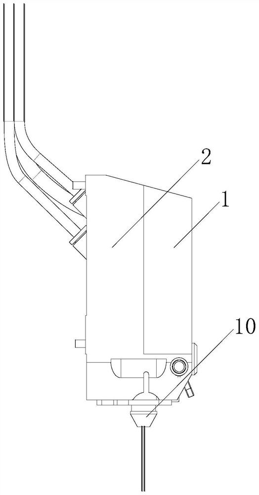
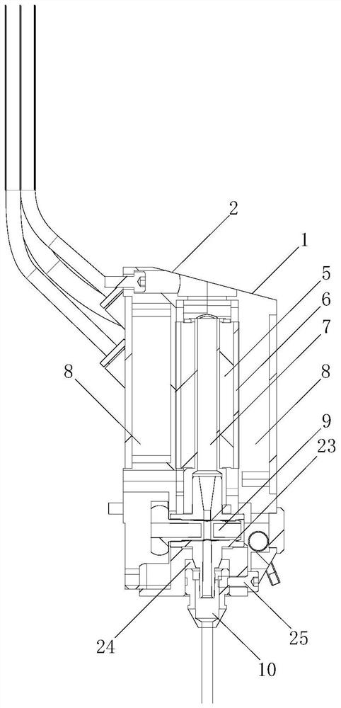
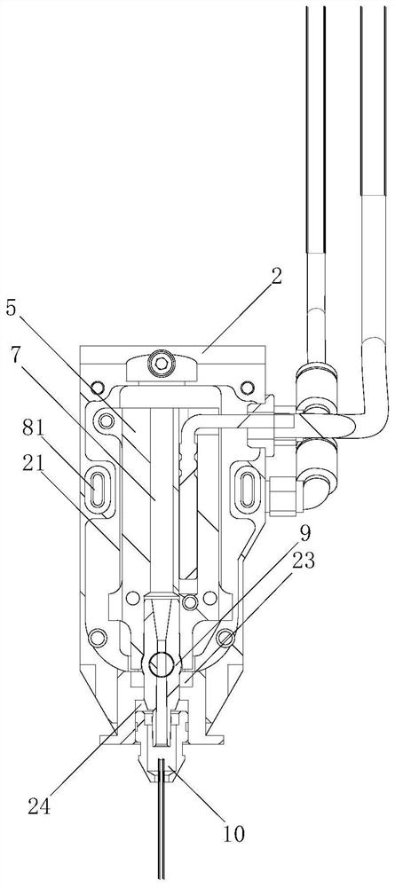
[0027] Embodiment 1: see Figure 1 to Figure 4 , a glue cooling device without condensed water, comprising a cooling device and a dispensing mixing tube 7 to be installed, the cooling device mainly consists of a housing, an internal cooling block 5, two cooling fins 6 and two cooling water tanks 8 , the internal cooling block 5 adopts a heat-conducting metal with excellent thermal conductivity, such as a copper block, and the cooling sheet 6 is a semiconductor cooling sheet, which has the advantages of small size and good cooling effect. The casing is composed of the front casing 1 and the rear casing The housing 2 is composed of the front housing 1 and the rear housing 2. The front housing 1 and the rear housing 2 are fixedly connected by screws. The inner sides of the front housing 1 and the rear housing 2 are provided with installation grooves 21 matching with the cooling water tank 8. The cooling The cooling surfaces of the fins 6 are respectively fixed on the front and ba...


PUM


Abstract

The invention discloses a glue cooling device without condensate water. The glue cooling device comprises a cooling device body and a to-be-mounted dispensing mixing pipe, wherein the cooling device body is mainly composed of a shell, an internal cooling block, two refrigeration sheets and two heat dissipation water tanks, the refrigeration faces of the refrigeration sheets are fixed to the frontface and the back face of the internal cooling block respectively, the heat dissipation faces of the refrigeration sheets are tightly attached to the heat dissipation water tanks respectively, a fixedextension portion and limiting extension portions are arranged on the side face of the internal cooling block, a threaded hole is formed in the fixed extension portion, and the internal cooling blockis fixed to a rear shell body through a fastening screw matched with the threaded hole. Compared with the prior art, the structural stability of the internal cooling block in all directions is fullyconsidered, the contact area of the internal cooling block and the shell is greatly reduced while the coaxiality of components is guaranteed, the heat exchange effect between the internal cooling block and the shell is relieved, therefore, it is guaranteed that the shell is in a normal-temperature state, and the problem that condensate water drips from the surface of the glue cooling device is thoroughly solved.

Description

technical field [0001] The invention relates to the field of glue dispensers, in particular to a glue cooling device without condensed water. Background technique [0002] The glue dispenser is an automatic machine that drips and coats the fluid on the surface or inside of the product. AB glue is widely used in various fields of industry due to its short curing time and good bonding performance. However, when the AB glue is mixed, it will solidify soon, so if the equipment cannot discharge the mixed glue in time, it will block the dispensing equipment and cause losses, and the continuous discharge of the mixed glue will cause glue waste. Therefore, in order to delay the reaction speed of AB glue after mixing, a cooling device is usually installed on the outside of it. There is a problem in the existing glue cooling device, because the internal cooling causes the overall temperature of the shell to be low, and it will be lower than normal temperature. Water droplets will be ...

Claims


Application Information

Patent Timeline
IPC IPC(8): B05C5/00B05C5/02
CPCB05C5/001B05C5/02
Inventor 王辉朱鸿彭玉江
Owner 成都苔岑智能设备有限公司
Learn More