

Piling method and piling device for borehole pump pouring large flow concrete ring pile
A large flow, drilling pump technology, applied in the direction of sheet pile wall, building, foundation structure engineering, etc., can solve problems such as laborious, difficult to form holes and piles, and expensive machinery
- Summary
- Abstract
- Description
- Claims
- Application Information
AI Technical Summary
Problems solved by technology
Method used
Image

Examples
specific Embodiment approach 1
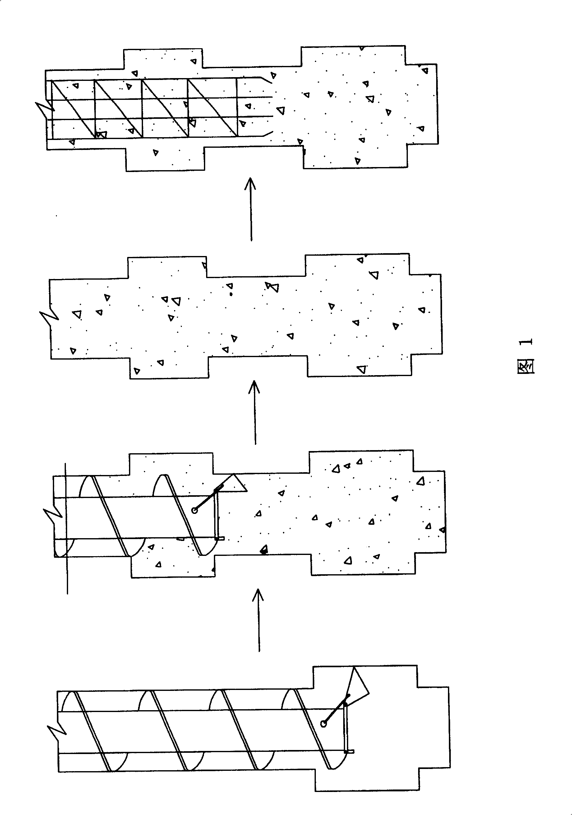
[0005] Specific embodiment one: (referring to Fig. 1) the method of this embodiment is realized through the following steps: one, the auger drilling machine drills to the design elevation and then lifts the drilling tool and opens the movable drill bit plate expander that is arranged on both sides of the drill bit blade. Hole; 2. At the same time as step 1, start the mud pump to press the grout and move the drilling tool up and down, so that the drilling tool falls back to the bottom of the hole, and then lift the drilling tool. The lower end of the drilling tool is 30-50cm away from the bottom of the hole; 3. Start the concrete pump pressure Concrete pouring, lifting the drilling tool to the upper edge of the expanding body while pressing the filling; 4. Retract the movable drill bit plate and stop grouting (at this time, the air compressor tube should be replaced or the nozzle has a check valve); 5. Carry out secondary diameter expansion when lifting the drilling tool to the ...
specific Embodiment approach 2
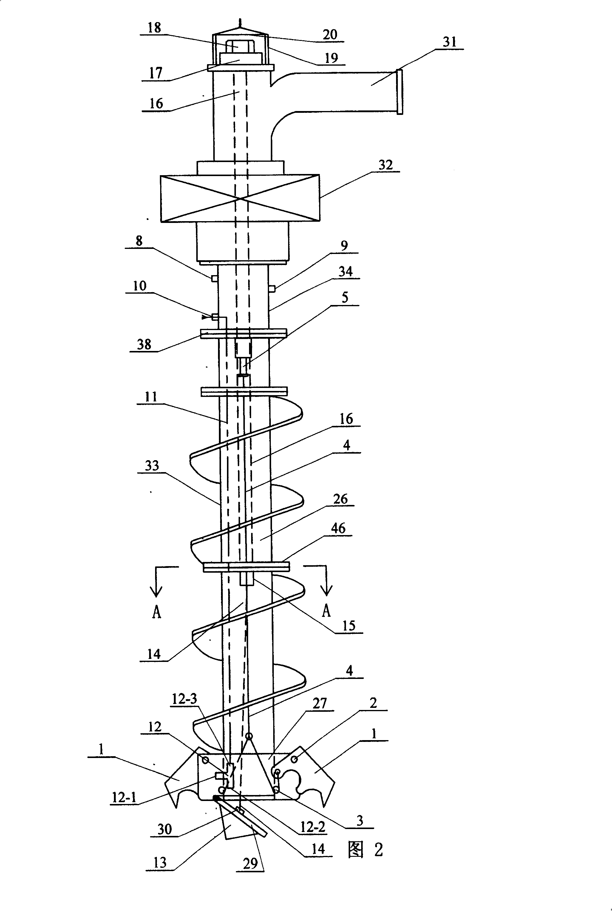
[0006] Specific embodiment two: (referring to Fig. 2, Figure 4) The piling device in this embodiment is controlled by the movable drill bit plate 1, the movable shaft 2, the orientation shaft 3, the rope 4, the hydraulic cylinder 5, the slurry delivery pipe 11, the three-way spray nozzle 12, the drill bit 13, and the discharge port cover plate Rope 14, flat steel 15, transmission rod 16, pressure bearing 17, nut 18, load-bearing basket 19, lifting beam 20, support plate 27 of movable drill bit plate, discharge port cover plate 29, lifting hook 30, concrete feed Pipe 31, reducer 32, hollow drill pipe 33, jacket 34, first seal ring 36, second seal ring 37, flange 38, hollow connecting shaft 39, rotating plate 44, drill pipe flange 46, third The sealing ring 47 and the fourth sealing ring 48 are composed, the lower end of the concrete feeding pipe 31 is fixed on the casing of the reducer 32, the hollow shaft of the reducer 32 is fixedly connected with the upper end of the hollow ...
specific Embodiment approach 3
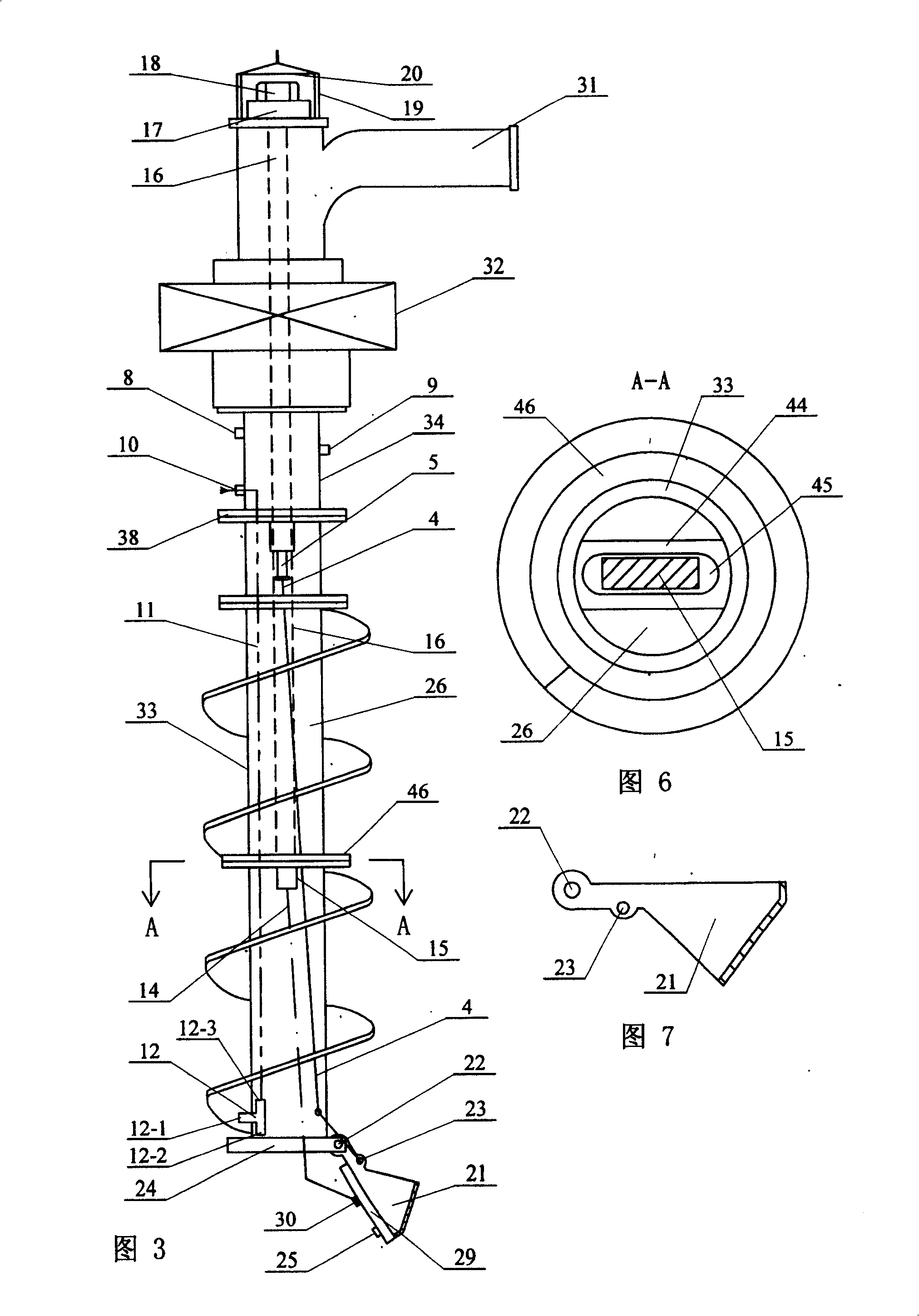
[0008] Specific embodiment three: (referring to Fig. 3~ Figure 5 ) The piling device of the present embodiment is composed of rope 4, hydraulic cylinder 5, slurry delivery pipe 11, three-way spray nozzle 12, drill bit 13, discharge port cover plate control rope 14, flat steel 15, transmission rod 16, pressure bearing 17. Nut 18, bearing basket 19, lifting beam 20, drill plate 21, connecting shaft 22, outer ring plate 24, discharge port cover plate 29, lifting hook 30, concrete feeding pipe 31, reducer 32, Hollow drill pipe 33, outer jacket 34, first seal ring 36, second seal ring 37, flange 38, hollow connecting shaft 39, rotating plate 44, drill pipe flange 46, third seal ring 47 and fourth The lower end of the concrete feeding pipe 31 is fixed on the casing of the reducer 32, the hollow rotor of the reducer 32 is fixedly connected with the upper end of the hollow connecting shaft 39, and the lower end of the hollow connecting shaft 39 is connected with the upper end of the ...
PUM
 Abstract
Description
Claims
Application Information