Supercharge Your Innovation With Domain-Expert AI Agents!

Strip lateral type light guide structure and surface source module

A light guide structure and side-firing technology, which is applied in optics, nonlinear optics, instruments, etc., can solve the problem of high cost of light source

Active Publication Date: 2008-11-19
IND TECH RES INST
View PDF1 Cites 0 Cited by
  • Summary
  • Abstract
  • Description
  • Claims
  • Application Information

AI Technical Summary

Problems solved by technology

This will at least keep the cost of such a traditional planar light source high

Method used


Image

  • Strip lateral type light guide structure and surface source module
  • Strip lateral type light guide structure and surface source module
  • Strip lateral type light guide structure and surface source module

Examples


Embodiment Construction

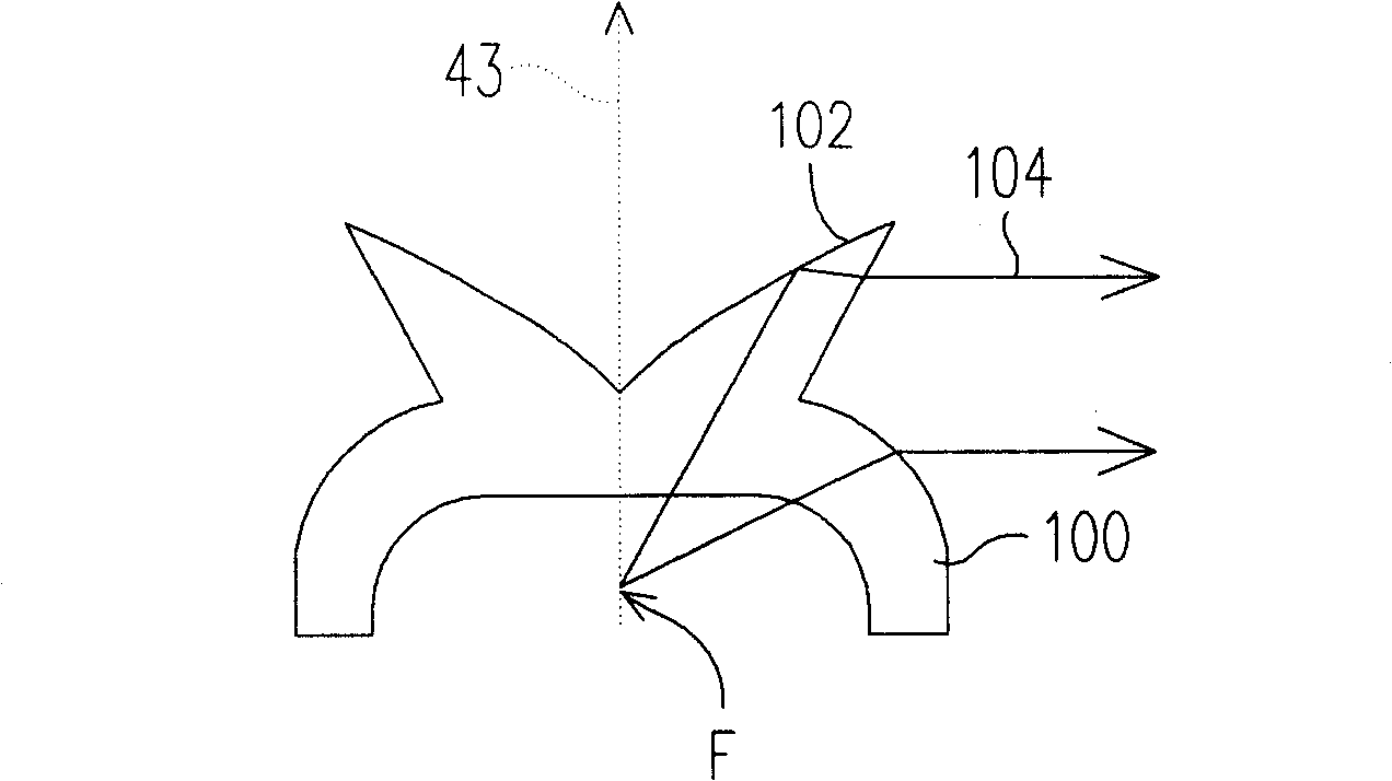
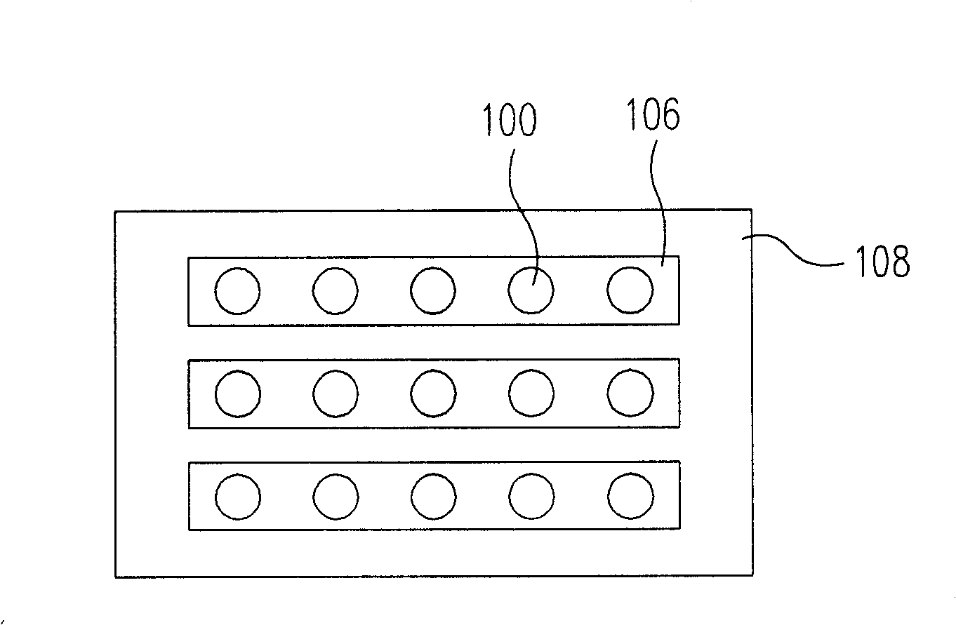
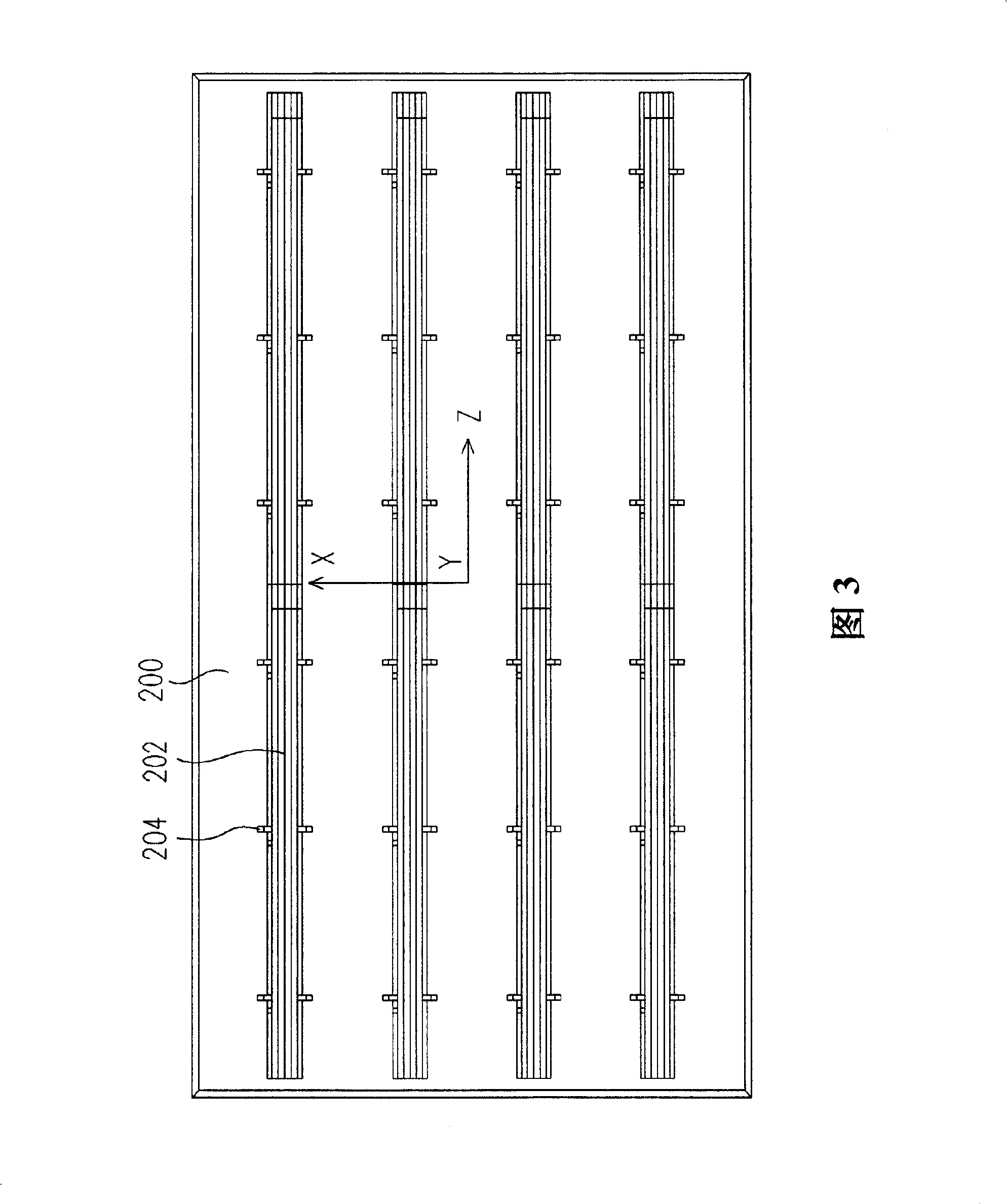
[0041] The strip-shaped side-firing light guide structure of the present invention changes the directional light source into a side-firing light source. This structure is especially suitable for large-scale planar light sources of LEDs as a light mixing module. This large planar light source module will include at least one light source, a strip-shaped side-firing light guide structure and a diffuser. This can at least make it easy to obtain a light source with uniform mixed light in a short distance, and has the characteristics of reducing cost and simple production.

[0042] At present, in the large-scale planar light source developed with LED light source, it is better to use total reflection and transparency to form a side-emitting light source for LED light source packaging design, but this packaging method will increase the cost and production complexity. Based on this factor, the present invention only needs to use a generally simple LED package, coupled with the strip-...


PUM


Abstract

The disclosed strip-shaped side-emergent light guide structure comprises: a strip-shaped light guide member with an upper and lower surface both vertical extended; on the cross section of former member, a first line segment on the upper surface, and a second and third line segments connected by a coupling member all on the lower surface. Wherein, the thickness distribution of the light guide member from lower to upper is reduced from the coupling member to side.

Description

technical field [0001] The invention relates to an illumination light source technology, and in particular to a strip-shaped side-firing light guide structure, which can be used to form a planar light source module. Background technique [0002] An actual light source structure generally includes a light guide structure, a diffuser and other components in addition to the light source, so as to guide the light emitted from the light source into a desired light-emitting form, so as to cooperate with the use of the configured device. For example, a plurality of light emitting diodes are used as the original light source, and then a light guide structure is used to form a planar light source. [0003] There are many applications of planar light sources, for example, they can be used in backlight modules of flat panel displays. The light guide structure, for example, can convert light emitted by a light emitting diode (Light Emitting Diode, LED) into a large planar light source ...

Claims


Application Information

Patent Timeline
Patent Type & Authority Patents(China)
IPC IPC(8): G02F1/1335
Inventor 姜雅惠陈秋伶殷尚彬胡鸿烈
Owner IND TECH RES INST
Features
  • R&D
  • Intellectual Property
  • Life Sciences
  • Materials
  • Tech Scout
  • Unparalleled Data Quality
  • Higher Quality Content
  • 60% Fewer Hallucinations
Learn More