
Measuring method and system for achieving blood pressure continuous measurement of pulse wave conduction time

A technology of conduction time and measurement system, applied in the measurement of pulse rate/heart rate, diagnostic record/measurement, catheter, etc., can solve the problem of high power consumption of pulse wave sensor, increase the physical and mental load of the subject, and affect the accuracy of measurement data and other problems to achieve the effect of reducing interference, reducing power consumption, and improving accuracy

Inactive Publication Date: 2008-11-26
AVIATION MEDICINE INST AIR FORCE PLA +1
View PDF3 Cites 0 Cited by
  • Summary
  • Abstract
  • Description
  • Claims
  • Application Information

AI Technical Summary

Problems solved by technology

[0007] In the prior art, the ECG sensor is usually placed on the chest of the individual under test, and the pulse wave sensor is placed on the wrist or the instep. Frequently moving hands, feet and limbs will cause great motion interference to the sensors installed on them, which will affect the accuracy of the measurement data. At the same time, there is a problem of high power consumption of the pulse wave sensor during continuous testing for a long time, especially when the pulse wave When the wave sensor device is powered by a small dry battery, it is difficult to maintain a long-term power supply of more than tens of hours
In addition, the continuous test in the homework will also increase the physical and mental load of the testee.

Method used


Image

  • Measuring method and system for achieving blood pressure continuous measurement of pulse wave conduction time
  • Measuring method and system for achieving blood pressure continuous measurement of pulse wave conduction time
  • Measuring method and system for achieving blood pressure continuous measurement of pulse wave conduction time

Examples


Embodiment 1

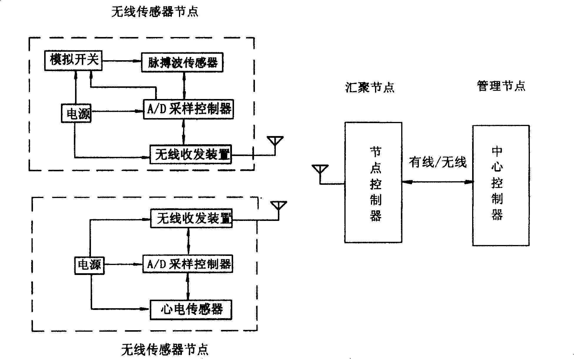
[0036] The sensor node data in this example is transmitted to the node controller through the wireless sensor network.

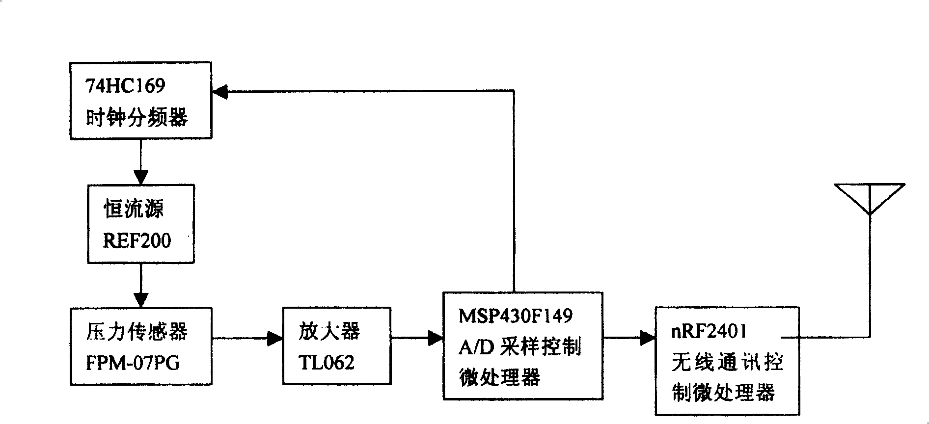
[0037] image 3 It is the hardware structure diagram of the wireless pulse wave sensor node: the pulse wave sensing element is connected to the A / D sampling control microprocessor through the amplifier, the A / D sampling control microprocessor is connected with the wireless communication control microprocessor, and the wireless communication microprocessor is connected with the wireless communication control microprocessor. The node controller set on the network aggregation node is connected to the wireless network, the sampling frequency signal output terminal of the A / D sampling control microprocessor is connected to the clock frequency divider to form an analog switch synchronous with the sampling frequency, and the constant current of the pulse wave sensor The source power is connected to the analog switch which can be turned off and on.

[0038] In this...

Embodiment 2

[0058] The data collected by the sensor nodes in this example is transmitted to the node controller through the wired network.

[0059] Figure 8 It is a schematic diagram of the hardware structure of the pulse wave sensing node in this example. The pulse wave sensing element is connected to the A / D sampling control microprocessor through the amplifier, and the sampling frequency signal output terminal of the A / D sampling control microprocessor is connected to the clock frequency divider. An analog switch synchronous with the sampling frequency is formed, the constant current source power supply of the pulse wave sensor is connected to the analog switch which can control its shutdown and opening, and the A / D sampling control microprocessor is wired with the node controller through the USB interface.

[0060] Figure 9 It is a schematic diagram of the hardware structure of the ECG sensor node. The ECG signal instrumentation amplifier is connected to the A / D sampling control mi...


PUM


Abstract

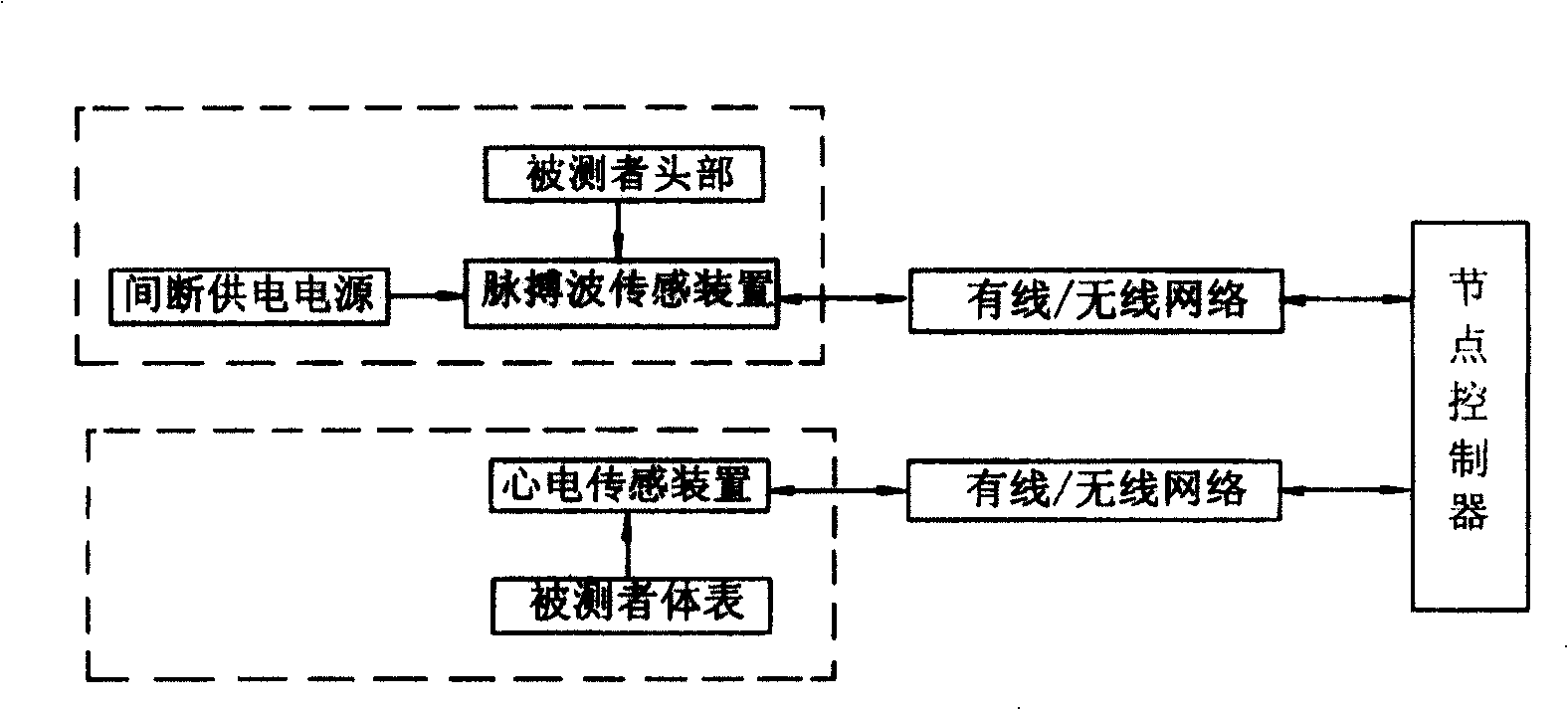
The pulse wave conducting time measuring method and system for the continuous measurement of blood pressure includes setting pulse wave sensor on the head of the testee, setting electrocardiac and pulse wave sensors in different network nodes, setting controlling computer system, connecting the sensors via the node controllers and communication protocol with the computer system, and adopts power saving intermittent power supply scheme. The present invention is suitable for measuring the pulse wave conducting time in operation condition, has raised measurement accuracy, low power consumption and reduced testee load, and is favorable to the real-time continuous measurement and monitoring of several sensing devices and several tested targets.

Description

technical field [0001] The invention belongs to a measuring method and system of pulse wave transit time of human body, in particular to a measuring method and system of pulse wave transit time for realizing continuous measurement of blood pressure. Background technique [0002] Blood pressure is an important parameter that reflects the function of the human circulatory system. Especially in military medical applications, it is very meaningful to be able to achieve non-invasive continuous measurement of blood pressure under normal operating conditions. [0003] Pulse wave velocity measurement of blood pressure is a non-invasive continuous measurement method. As early as 1922, it was discovered that pulse wave velocity (PWTV) or transit time (PWTT) is related to arterial blood pressure, and also related to blood vessel volume and blood vessel wall elasticity; In 1957, it was proposed that within a certain range, there is a linear relationship between PWTT and arterial blood p...

Claims


Application Information

Patent Timeline
Patent Type & Authority Patents(China)
IPC IPC(8): A61B5/024A61B5/0402A61B5/02A61B5/00
Inventor 俞梦孙姬军杨福生陶祖莱谢敏毕大成
Owner AVIATION MEDICINE INST AIR FORCE PLA
Learn More