Measuring method and system for achieving blood pressure continuous measurement of pulse wave conduction time
A technology of conduction time and measurement system, which is applied in the measurement of pulse rate/heart rate, diagnostic record/measurement, catheter, etc., can solve the problem that the pulse wave sensor consumes a lot of power, increases the physical and mental load of the subject, and affects the accuracy of measurement data. and other problems to achieve the effect of reducing power consumption, improving accuracy and reducing interference
- Summary
- Abstract
- Description
- Claims
- Application Information
AI Technical Summary
Problems solved by technology
Method used
Image
Examples
Embodiment 1
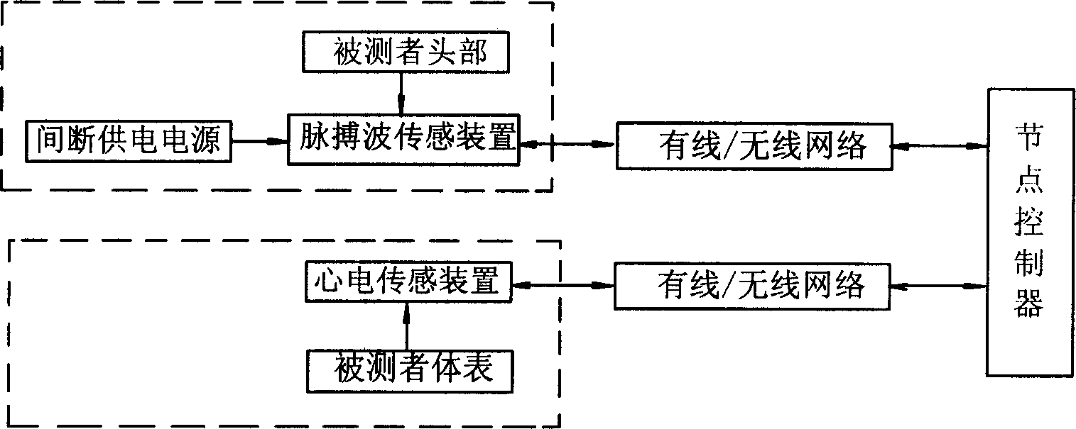
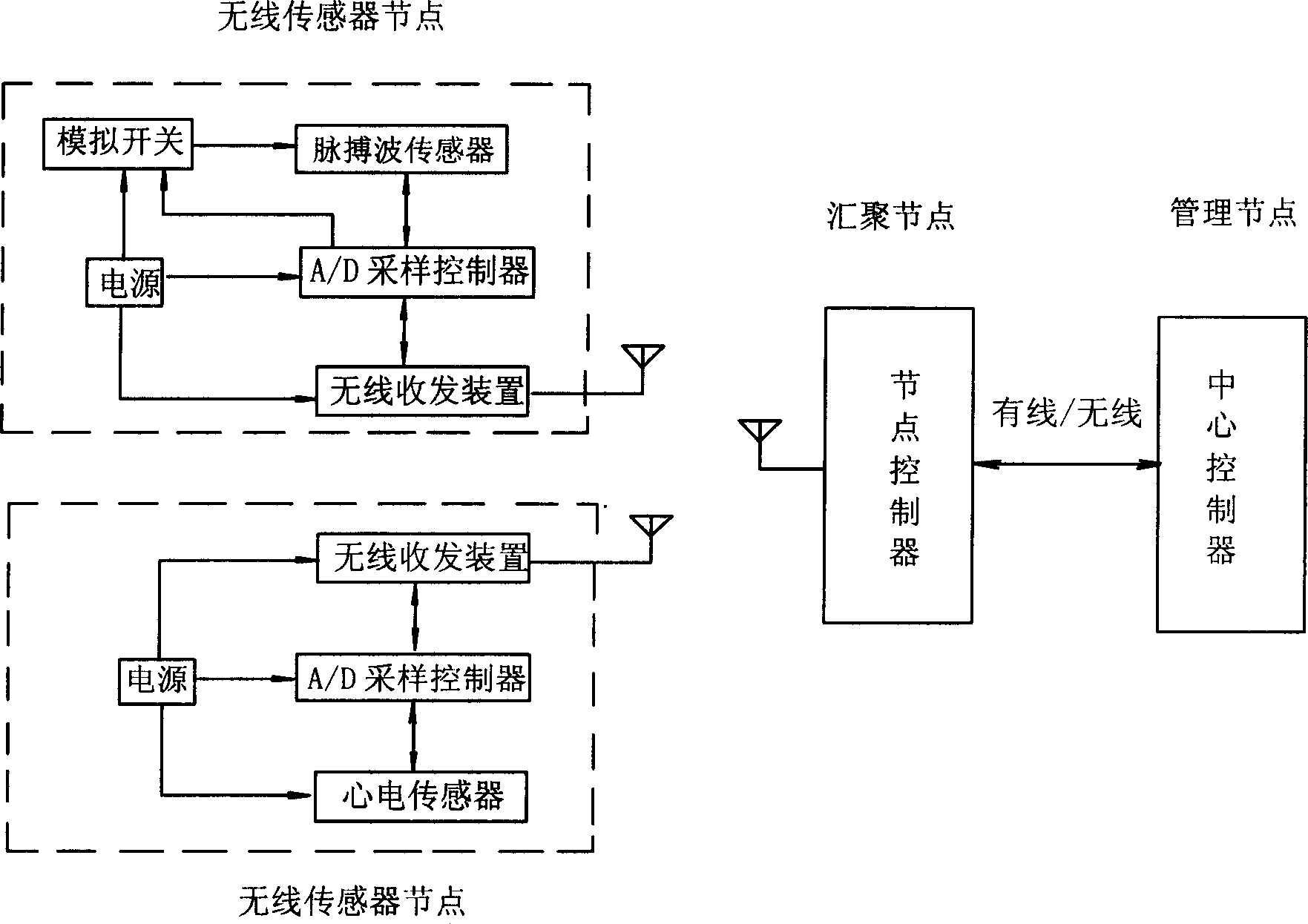
[0036] The sensor node data in this example is transmitted to the node controller through the wireless sensor network.
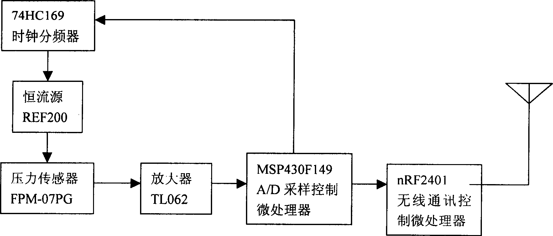
[0037] image 3 It is the hardware structure diagram of the wireless pulse wave sensor node: the pulse wave sensing element is connected to the A / D sampling control microprocessor through the amplifier, the A / D sampling control microprocessor is connected with the wireless communication control microprocessor, and the wireless communication microprocessor is connected with the wireless communication control microprocessor. The node controller set on the network aggregation node is connected to the wireless network, the sampling frequency signal output terminal of the A / D sampling control microprocessor is connected to the clock frequency divider to form an analog switch synchronous with the sampling frequency, and the constant current of the pulse wave sensor The source power is connected to the analog switch which can be turned off and on.
[0038] In this...
Embodiment 2
[0058] The data collected by the sensor nodes in this example is transmitted to the node controller through the wired network.
[0059] Figure 8 It is a schematic diagram of the hardware structure of the pulse wave sensing node in this example. The pulse wave sensing element is connected to the A / D sampling control microprocessor through the amplifier, and the sampling frequency signal output terminal of the A / D sampling control microprocessor is connected to the clock frequency divider. An analog switch synchronous with the sampling frequency is formed, the constant current source power supply of the pulse wave sensor is connected to the analog switch which can control its shutdown and opening, and the A / D sampling control microprocessor is wired with the node controller through the USB interface.
[0060] Figure 9 It is a schematic diagram of the hardware structure of the ECG sensor node. The ECG signal instrumentation amplifier is connected to the A / D sampling control mi...
PUM
 Abstract
Description
Claims
Application Information
 - R&D
- Intellectual Property
- Life Sciences
- Materials
- Tech Scout
- Unparalleled Data Quality
- Higher Quality Content
- 60% Fewer Hallucinations
Browse by: Latest US Patents, China's latest patents, Technical Efficacy Thesaurus, Application Domain, Technology Topic, Popular Technical Reports.
© 2025 PatSnap. All rights reserved.Legal|Privacy policy|Modern Slavery Act Transparency Statement|Sitemap|About US| Contact US: help@patsnap.com


