Severing machine

A technology for cutting machines and knives, applied in sawing equipment, metal sawing equipment, sawing machine devices, etc., can solve the problems of worker discomfort and commodity value decline, and achieve commodity value maintenance, sound elimination, and comfortable use Effect

Inactive Publication Date: 2008-12-17
MAKITA CORP
View PDF8 Cites 0 Cited by
  • Summary
  • Abstract
  • Description
  • Claims
  • Application Information

AI Technical Summary

Problems solved by technology

However, the upper dead center and the lower dead center of the main body also cause shaking between the safety cover and the connecting member, making noise during use, or the connecting member vibrating, causing discomfort to the worker and causing a decrease in the value of the product.

Method used


Image

  • Severing machine
  • Severing machine
  • Severing machine

Examples


Embodiment Construction

[0017] Embodiments of the present invention will be described below based on the drawings.

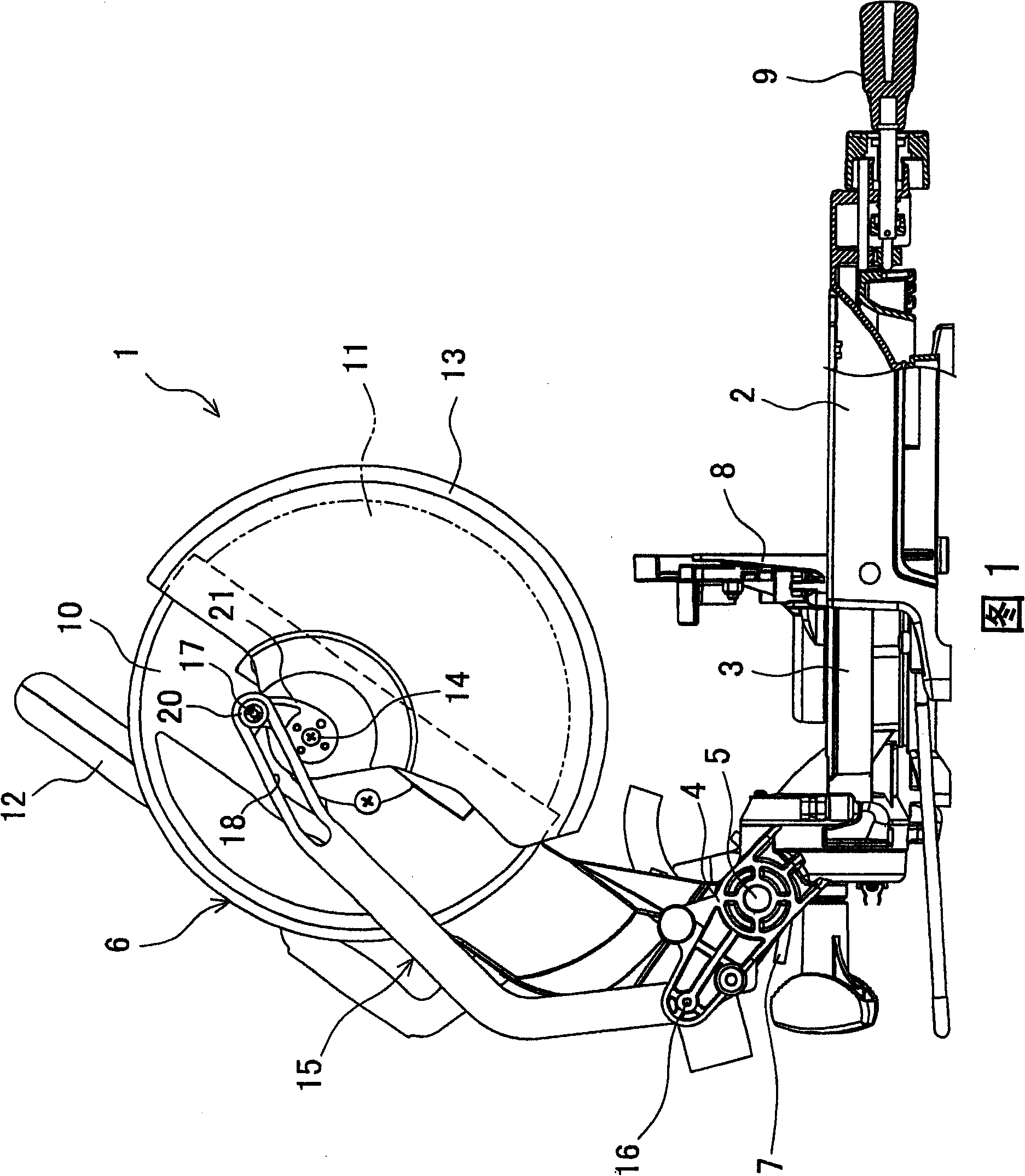
[0018] 1 is an explanatory view of a table-type circular sawing machine as an example of a cutting machine seen from the side. (Left side in the drawing) An arm 4 is erected, and a main body 6 is pivotally mounted to the middle portion of the arm 4 via a support shaft 5 so as to be movable up and down. The main body 6 is loaded toward the top dead center position in FIG. 1 by the torsion spring 7 arranged on the fulcrum 5 part. 8 is a guide fence erected on the base 2 in the left-right direction so as to traverse the turntable 3 , and 9 is an operation lever for rotating and operating the turntable 3 .

[0019] The main body 6 has: a sawtooth chamber 10 equipped with a motor not shown in the figure; a disc-shaped sawtooth 11 (cutter) which covers approximately half of the obliquely rear side at the top dead center by the sawtooth chamber 10, and is performed by the motor. Rotation; h...


PUM


Abstract

PROBLEM TO BE SOLVED: To keep preferable use feeling or commercial value by preventing the generation of sound and the like at the time of opening / closing a safety cover. SOLUTION: A link plate 15 laid between an arm and the safety cover is journaled by loosely inserting a stepped bolt 17 externally equipped with a sleeve 19 and a washer 20 into a long groove 18 provided on an end portion side of the link plate 15 to be screwed with a coupling piece 21 of the safety cover, on the safety cover side. The long groove 18 is formed to have width W larger than a diameter of the sleeve 19 so as to ensure sliding of the stepped bolt 17 even when the link plate 15 is deformed due to external force. An end portion on an engaging side of the stepped bolt 17 in the long groove 18 is formed from a tapered portion 22 decreasing width toward a termination, and the arc-shaped termination 23 to which the tapered portion 22 is continued and the sleeve 19 is fitted. COPYRIGHT: (C)2007,JPO&INPIT

Description

technical field [0001] The present invention relates to a cutter, such as a cutter or a desktop circular saw, in which a main body including a rotary-driven cutting blade is vertically movable on an arm portion erected on a base on which a workpiece is placed. Background technique [0002] For example, in a table-top circular sawing machine, a disc-shaped arm with a rotation drive by a motor is provided in a state where it is movable up and down by a support shaft and loaded to the upper dead point by a loading mechanism on an arm protruding from the rear of the base. The main body of the sawtooth (cutter) can cut the workpiece placed on the base by lowering the operating main body. In addition, "upper dead point" refers to the upper limit position where the main body stops when the lowering operation is not performed, and "lower dead point" described later refers to the lower limit position where the main body stops after the lowering operation is performed. [0003] And, ...

Claims


Application Information

Patent Timeline
Patent Type & Authority Patents(China)
IPC IPC(8): B23D47/00B23D45/04B27G19/02B27B5/29
Inventor 沼田文年
Owner MAKITA CORP
Why Eureka
Try Eureka