Mining lamp with flasher
A flickering light source and miner's lamp technology, which is applied to electric light sources, electric lighting devices with built-in batteries, and built-in batteries, etc., can solve the problems of prolonging the use time of miner's lamps, and achieve good promotion and application value, convenient contact, and convenient use. Effect
- Summary
- Abstract
- Description
- Claims
- Application Information
AI Technical Summary
Problems solved by technology
Method used
Image

Examples
Embodiment 1
[0027] Embodiment 1: The miner's lamp with flashing light source of the present invention contains a battery, a main light source and an auxiliary light source. The battery is connected to the main light source and the auxiliary light source through a switch circuit. The switch circuit is controlled by a microprocessor, and the switch circuit contains control buttons. , microprocessor and switch control elements, and the control buttons are installed on the battery shell of the miner's lamp.
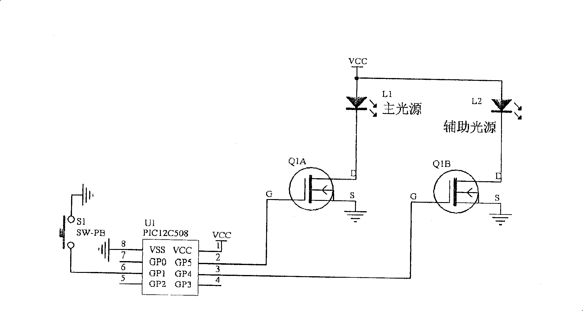
[0028] see figure 1 , is one of the schematic diagrams of the miner's lamp circuit with the flickering light source in this embodiment: the microprocessor adopts PIC12C508, the switch control element adopts a field effect transistor, the VCC port of PIC12C508 is connected to the power supply (i.e. the battery positive pole), and the VSS port of PIC12C508 is grounded (i.e. Battery negative pole), one I / O port GP1 of PIC12C508 is connected to the control button S1, the other end of the con...
Embodiment 2
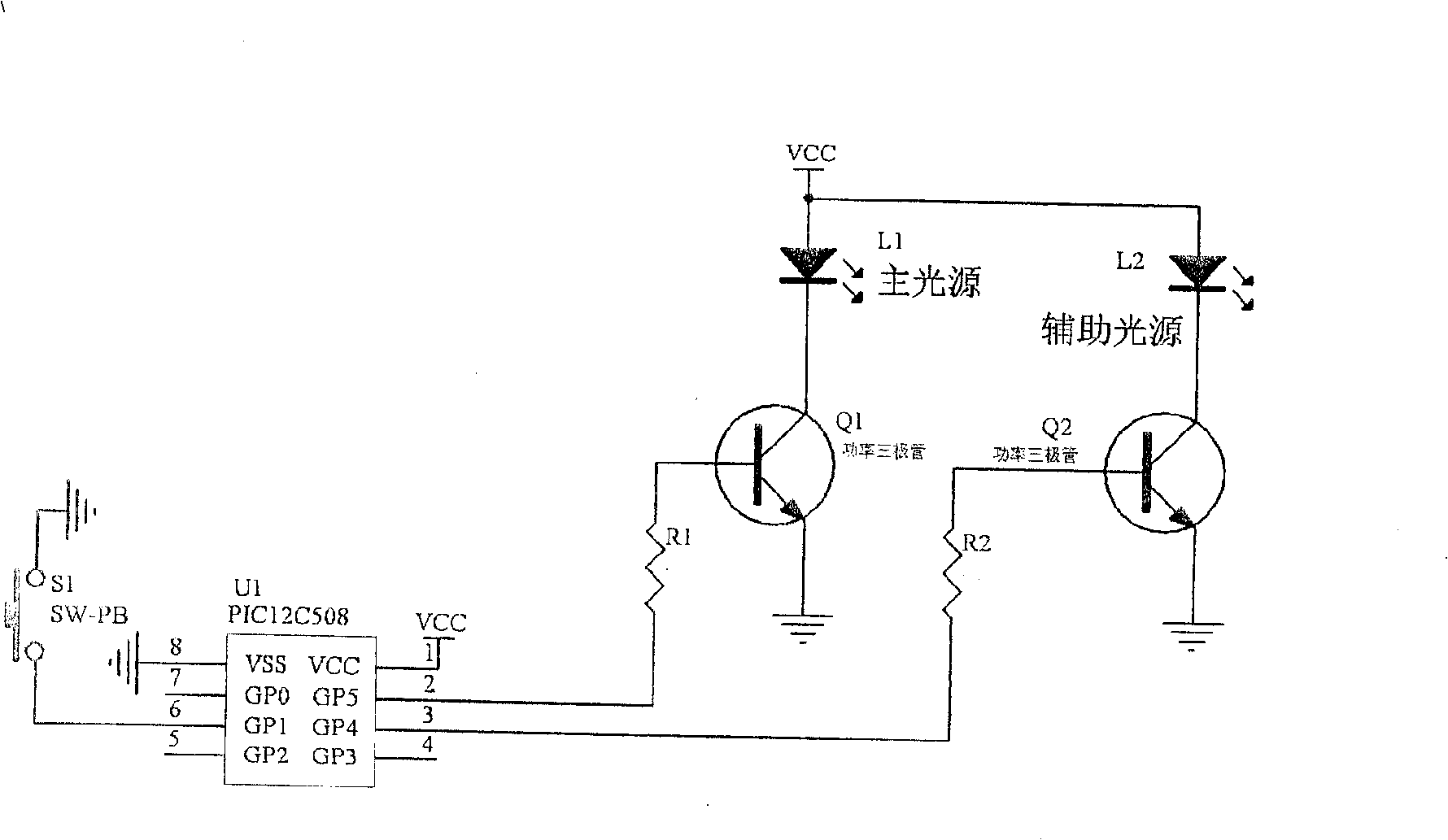
[0042] Embodiment two: see figure 2 , the structure of this embodiment is basically the same as that of Embodiment 1, with one difference: wherein the switch control element adopts a power triode, and the control bases of the power transistors Q1 and Q2 are respectively connected to two microprocessors through current-limiting resistors R1 and R2. I / O output ports, the emitters of the power transistors Q1 and Q2 are connected to the negative pole of the battery, and the collectors are respectively connected to the positive pole of the battery through the main light source L1 and the auxiliary light source L2. The power triode can be replaced by a Darlington tube (composite tube).
Embodiment 3
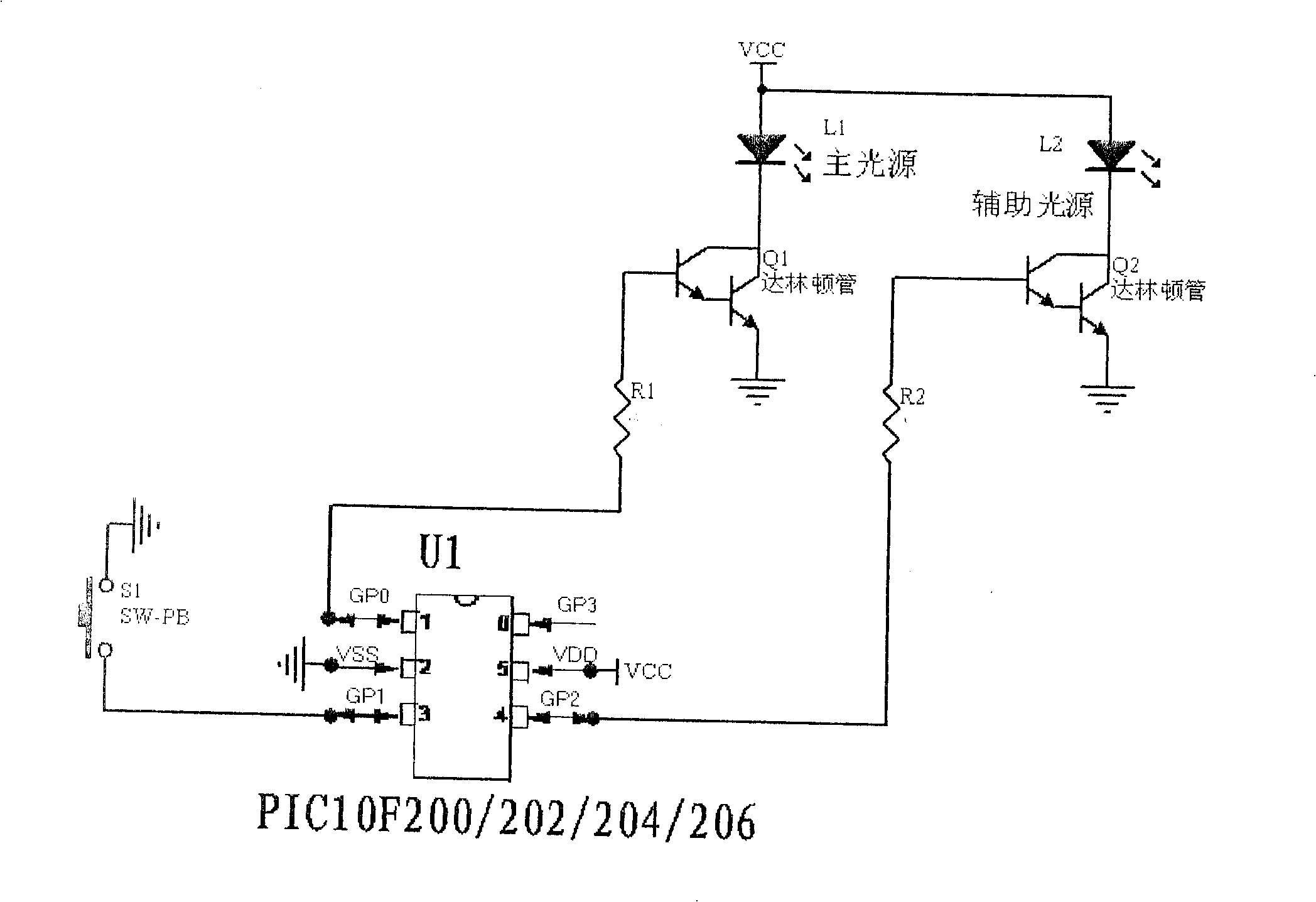
[0043] Embodiment three: see image 3 The difference between this embodiment and the above-mentioned embodiments is that the microprocessor can use any chip in PIC10F200 / 202 / 204 / 205, and the switch control element can also use a power triode, or a field effect tube. The specific connection relationship is: the VCC port of the microprocessor is connected to the power supply, which is the positive pole of the battery, the VSS port is grounded, which is the negative pole of the battery, one I / O port GP1 of PIC10F2XX is connected to the control button S1, the other end of the control button S1 is grounded, and the two I / O ports of PIC10F2XX are connected to the ground. The / O output ports GP0 and GP2 are respectively connected to the trigger control ends of the two switch control elements, and the output ends of the two switch control elements are respectively connected in series with the main light source and the auxiliary light source and connected between the two poles of the b...
PUM
 Abstract
Description
Claims
Application Information
 - R&D
- Intellectual Property
- Life Sciences
- Materials
- Tech Scout
- Unparalleled Data Quality
- Higher Quality Content
- 60% Fewer Hallucinations
Browse by: Latest US Patents, China's latest patents, Technical Efficacy Thesaurus, Application Domain, Technology Topic, Popular Technical Reports.
© 2025 PatSnap. All rights reserved.Legal|Privacy policy|Modern Slavery Act Transparency Statement|Sitemap|About US| Contact US: help@patsnap.com