Compound heat-exchanger

A heat exchanger and composite technology, applied in indirect heat exchangers, lighting and heating equipment, etc., can solve the problems that liquid plugs and air bubbles cannot coexist, limited effective contact area, limited effective heat dissipation area, etc., and achieve small size, Effect of increased application range and high cooling performance

Inactive Publication Date: 2008-12-24
ENERGY RES INST OF SHANDONG ACAD OF SCI
View PDF8 Cites 0 Cited by
  • Summary
  • Abstract
  • Description
  • Claims
  • Application Information

AI Technical Summary

Problems solved by technology

Of course, there are many deficiencies in the oscillating heat pipe, such as its diameter cannot be too large or too small, because when it is too large, the liquid plug and air bubbles cannot coexist under the action of surface tension, and when it is too small, it is necessary to increase the evaporation pressure to overcome the capillary force. Thus affecting the oscillation effect; the tube-type oscillating heat pipe cannot effectively dissipate heat on the flat heating surface, and the plate-type oscillating heat pipe can dissipate heat on the flat heating surface, but its effective contact area with the heating surface is limited, which limits its performance.
[0005] Based on the above analysis, we can see that micro-groove group evaporative heat transfer is an effective means to solve high heat flow and heat generation, but the condensation cycle of its steam is very demanding. If we can condense it immediately when the steam is generated, it is bound to be Make the system more efficient; on the other hand, the oscillating heat pipe has excellent heat transfer performance, but its processing technology is not yet mature, and its effective heat dissipation area is limited for the flat heating surface

Method used


Image

  • Compound heat-exchanger
  • Compound heat-exchanger
  • Compound heat-exchanger

Examples


Embodiment Construction

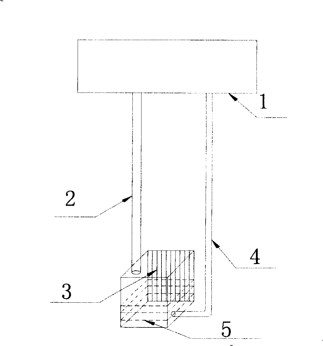
[0042] Such as figure 1 As shown, this mode is a general way of evaporating and cooling microgrooves. Its main working principle is that the wall surface with microgrooves 3 is in direct contact with the heating element, and the liquid working substance 5 in the cavity evaporates on the surface of microgrooves 3. The heat of the heating element is taken out, and then the steam enters the cooling device 1 along the pipeline 2 to condense, the system heat is taken out by the cooling device 1, and the liquid working medium 5 condenses and flows back into the square cavity. The structure of this scheme is simple, but we know that the biggest problem in this scheme is whether the heat can be taken out in time and the working medium can be condensed to ensure circulation. This is the basis for ensuring the normal operation of this mode. Look, it is difficult to ensure its effective operation under high heat generation. The reason is that under high heat generation, the steam cannot ...


PUM


Abstract

The invention relates to a composite heat exchanger, which includes the shell which opens a hatch on the top and with a hollow cavity and the superior cover which meet with the shell, between the shell and the cover seals by the water, and packaging the shell and cover together to compose a heat exchanger, whose characterized is that setting a oscillating heat pipe through the cover, the heat end of the oscillation heat pipe installs in the groove of cover, the wall of the shell is the micro-porous structure which can produce capillary force.

Description

technical field [0001] The invention relates to the field of microscale heat transfer, in particular to a composite heat exchanger. Background technique [0002] With the continuous advancement of science and technology, the density of electronic components in various electronic products is getting higher and higher, and its high calorific value has gradually become a bottleneck restricting its further development. In this case, the micro heat exchange system came into being. In various micro heat exchange systems, most researchers are engaged in micro heat pipe technology, including capillary type, forced vibration (oscillation) type and micro groove (group) internal heat pipe technology. Single-phase and phase transition research, and achieved a lot of research results. [0003] The calculation results show that the theoretical limit value of the evaporation heat flux inside the microgroove group has reached 1000W / cm 2 As mentioned above, at the same time, with the help ...

Claims


Application Information

Patent Timeline
Patent Type & Authority Patents(China)
IPC IPC(8): F28D15/02F28D15/04
CPCF28D15/0266F28D15/046
Inventor 张承武刘志刚管宁
Owner ENERGY RES INST OF SHANDONG ACAD OF SCI
Why Eureka
Try Eureka