Data center energy-saving cooling system based on heat pipe technology

A data center and cooling system technology, applied in the direction of cooling/ventilation/heating renovation, etc., can solve the problems of high indoor temperature, large structure, failure, etc., to achieve the effect of reducing operating costs, simple system structure, and power reduction

Active Publication Date: 2015-03-25
CHINA ACAD OF AEROSPACE AERODYNAMICS
View PDF8 Cites 11 Cited by
  • Summary
  • Abstract
  • Description
  • Claims
  • Application Information

AI Technical Summary

Problems solved by technology

But they have the following deficiencies and defects: 1) The evaporation section of the separated heat pipe is in the machine room, and the cooling section is arranged outside the machine room, so its installation and the location of the machine room have certain restrictions, and the machine room needs to be located on the top floor of the building or in the machine room There are open places on the outside of the surrounding walls for the installation of the system; 2) The operation of the system requires the indoor temperature to be higher than the outdoor temperature, so the system is completely ineffective in summer; 3) The structure of the entire system is relatively large and complex

Method used


Image

  • Data center energy-saving cooling system based on heat pipe technology
  • Data center energy-saving cooling system based on heat pipe technology

Examples


Embodiment Construction

[0018] Embodiments of the present invention will be further described below in conjunction with the accompanying drawings.

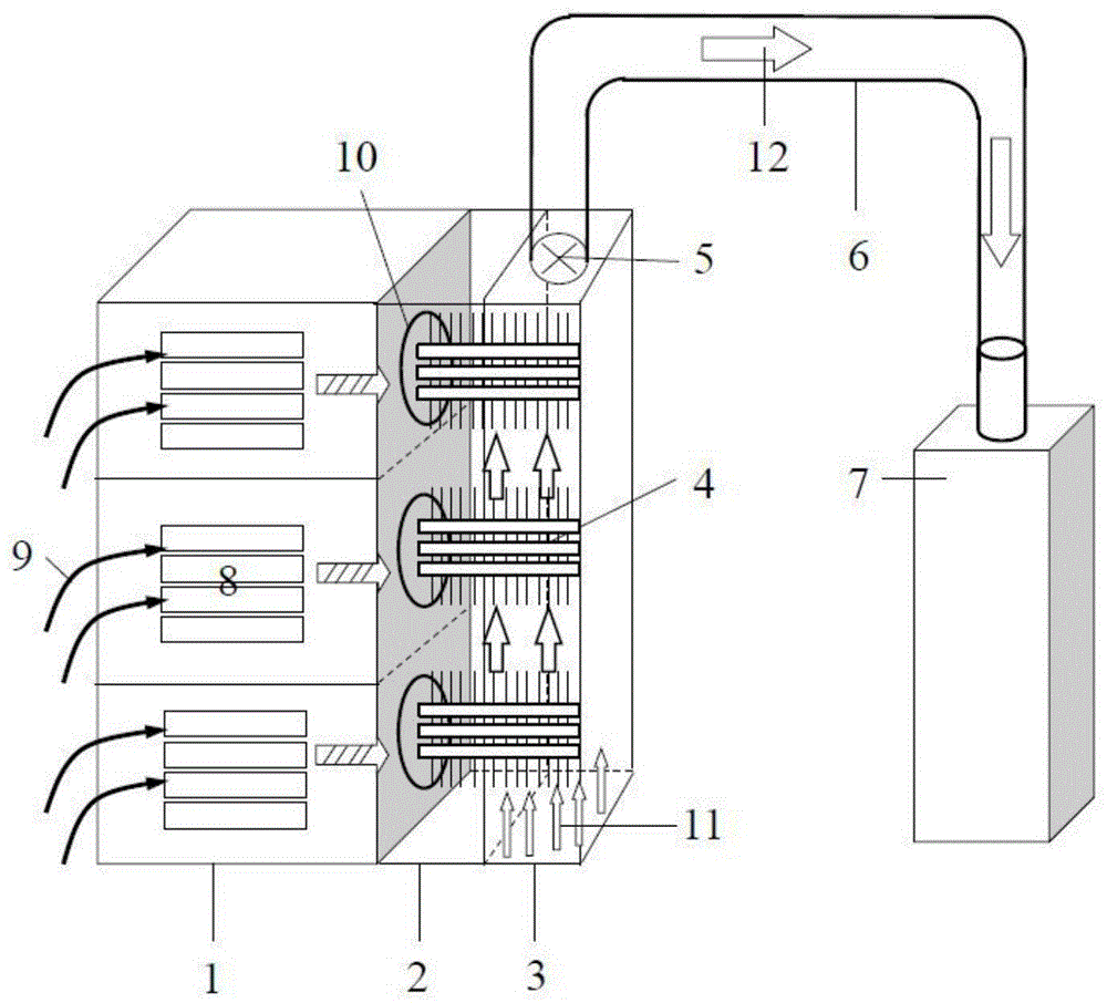
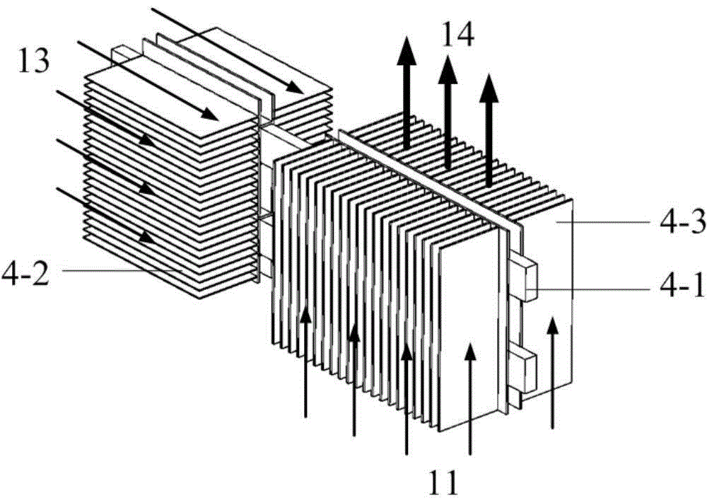
[0019] Such as figure 1 As shown, an energy-saving cooling system for a data center based on heat pipe technology includes an additional heating cabinet 2 , an additional refrigerator 3 , a heat pipe system 4 , an exhaust fan 5 , and a closed pipeline 6 . Adding a heating cabinet 2 to the rear of the cabinet 1, and installing a refrigerator 3 to connect to the rear of the heating cabinet 2, and the exhaust fan 5 is arranged at the junction of the additional cooling cabinet 3 and the closed pipeline 6, and the closed pipeline 6 will Adding freezer 3 is connected with machine room air conditioner 7. The heat pipe system 4 includes heat pipes 4-1 and fins, and the fins are divided into front row fins 4-2 and rear row fins 4-3. The first half of the heat pipe 4-1 and the front row of fins 4-2 constitute the evaporation section of the heat pipe system 4, wh...


PUM


Abstract

The invention relates to a data center energy-saving cooling system based on the heat pipe technology. The data center energy-saving cooling system comprises an additionally-installed heat cabinet, an additionally-installed refrigerator, a heat pipe system, an air exhaust fan and a closed pipeline. The additionally-installed heat cabinet is connected to the back of a cabinet, the additionally-installed refrigerator is connected to the back of the additionally-installed heat cabinet, one end of the closed pipeline is communicated with the upper end of the additionally-installed refrigerator, the other end of the closed pipeline is communicated with an air conditioner system, the air exhaust fan is installed at the joint of the additionally-installed refrigerator and the closed pipeline, and a vent hole is formed in the bottom of the additionally-installed refrigerator and used for being communicated with a floor air supplying system. The heat pipe system comprises a plurality of heat pipes. Each heat pipe comprises an evaporating section and a cooling section, wherein the evaporating section is located in the additionally-installed heat cabinet, the cooling section is located in the additionally-installed refrigerator, and one end of the heat pipe is connected with the back wall of the cabinet. The temperature of hot air mass exhausted out of an outlet in the back of the cabinet can be further reduced, the overall heat dissipation efficiency of a machine room is improved, and the power consumption of a refrigeration device for cooling a server in the machine room is reduced.

Description

technical field [0001] The invention belongs to the technical field of heat dissipation and heat pipes in computer rooms, and relates to an energy-saving cooling device and system for a data center based on heat pipe technology. Background technique [0002] The IDC computer room has now become an important part of the national economic development, and is the main pillar to promote the informatization and digitization of the national science and technology industry. With the development of the scale and integration of data centers, the power density of IT equipment in servers is increasing day by day, and the heat density is increasing rapidly. On the one hand, the electric power consumed by refrigeration equipment is increasing rapidly, and the energy consumption of computer rooms has attracted more and more attention; on the other hand, On the one hand, the problem of server heat dissipation will become more and more serious, and may even cause equipment shutdown due to e...

Claims


Application Information

Patent Timeline
Patent Type & Authority Applications(China)
IPC IPC(8): H05K7/20
Inventor 艾邦成俞继军薛志虎陈思员曲伟谢铭慧李炜
Owner CHINA ACAD OF AEROSPACE AERODYNAMICS
Why Eureka
Try Eureka