Turbo-compound system

A technology of turbo compound and power turbine, applied in clutch, clutch, fluid clutch, etc., can solve the problems of strong torque dependence, inability to apply uniform braking torque to the crankshaft, unevenness, etc.

Inactive Publication Date: 2008-12-31
VOITH TURBO GMBH & CO KG
View PDF5 Cites 2 Cited by
  • Summary
  • Abstract
  • Description
  • Claims
  • Application Information

AI Technical Summary

Problems solved by technology

[0004] Although these systems achieve a certain degree of braking effect during braking operations, it has been shown that the conversion of the exhaust gas power turbine to the compressor cannot apply a satisfactory uniform braking torque to the crankshaft
In contrast, in a system with a fixed hydrodynamic coupling impeller, the hydrodynamic coupling generates a braking torque when operating as a retarder, with which the crankshaft of the internal combustion engine brakes, this torque strongly depends on the speed and is thus also uneven of

Method used


Image

  • Turbo-compound system
  • Turbo-compound system

Examples


Embodiment Construction

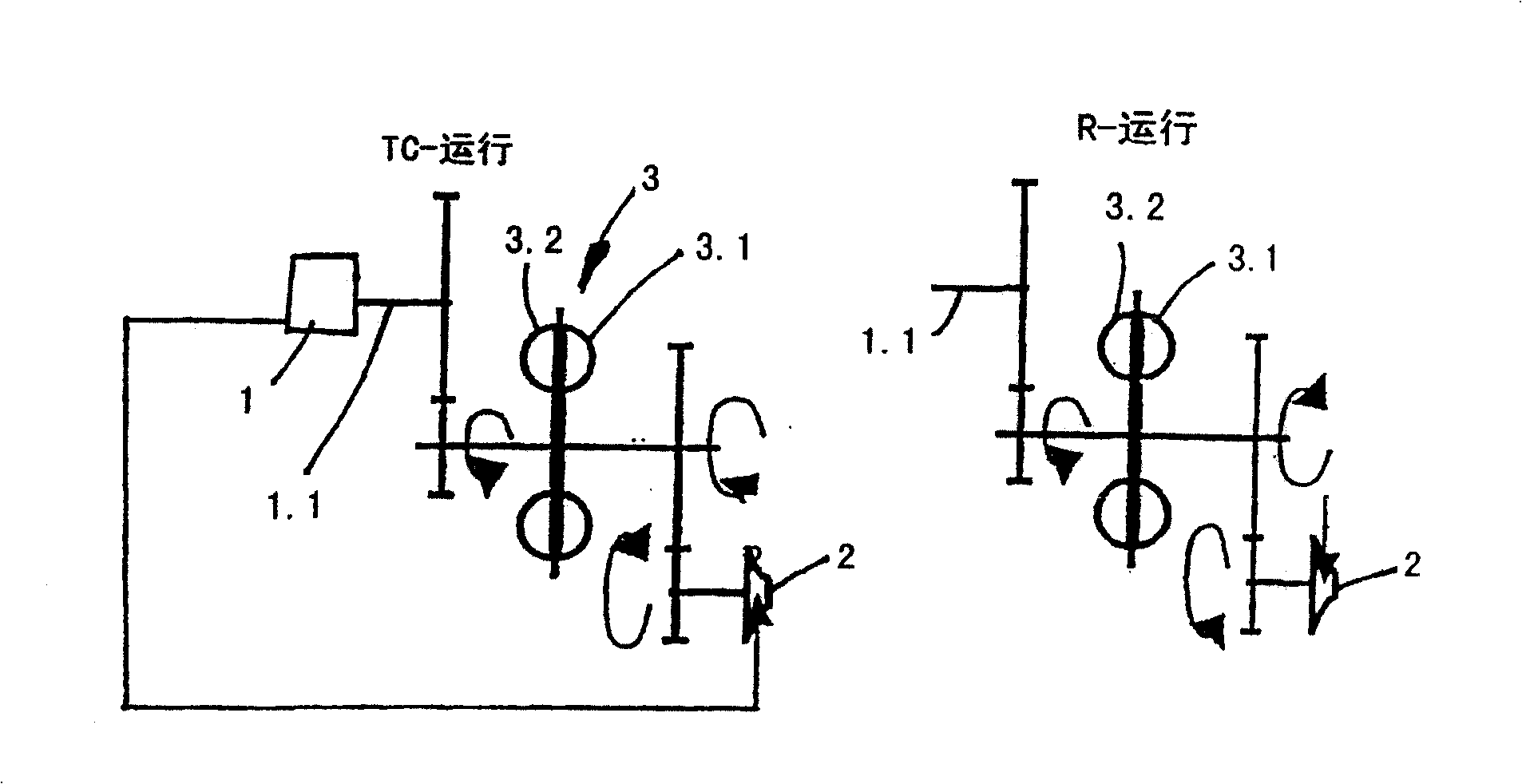
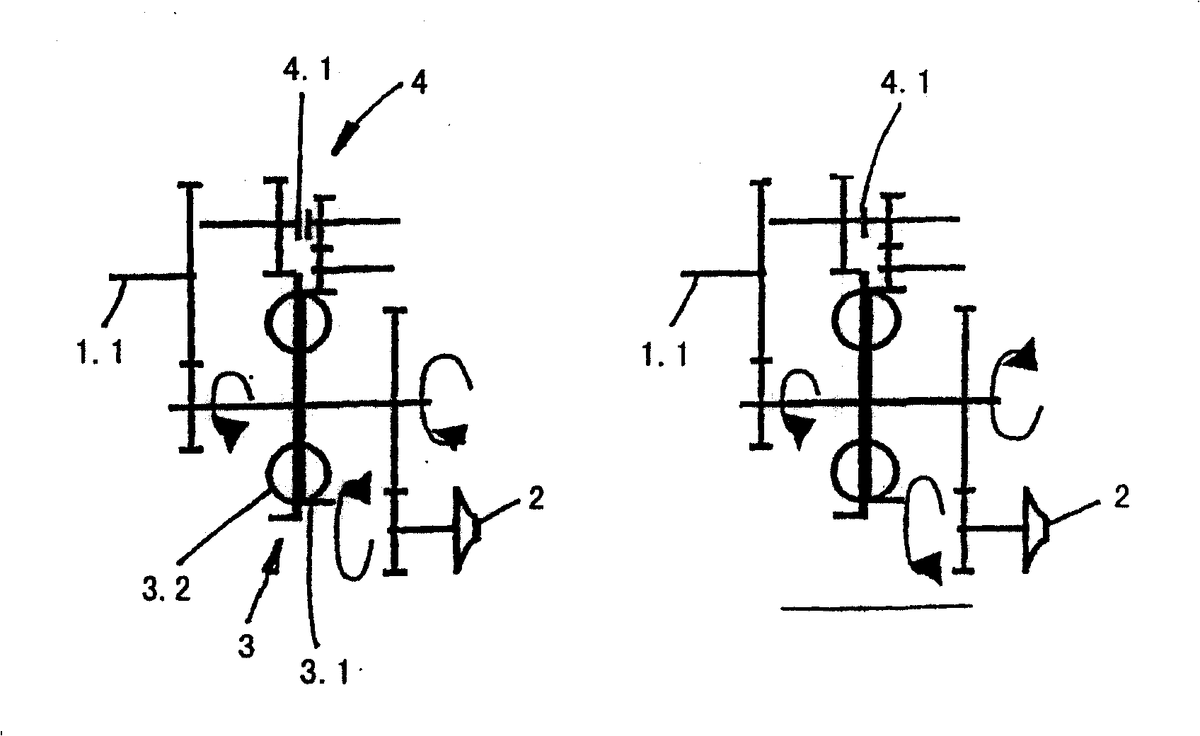
[0020] figure 1 represents a turbocompound system according to the invention, in which there is an internal combustion engine 1 , during turbocompound operation, the crankshaft 1 . The fluid coupling working chamber between the second wheel and the second wheel 3.2 is filled with working medium. On each side of the hydrodynamic coupling 3 there are speed shifting gears between the crankshaft 1.1 and the second wheel 3.2 and between the exhaust gas turbine 2 and the first wheel 3.1. As shown, in turbocompound operation, the targeted supply of exhaust gas flow to the exhaust gas turbine or to the turbine wheel of the exhaust gas turbine via a guide grid causes the first wheel 3.1 of the fluid coupling to rotate in a first direction of rotation.

[0021] On the contrary, in the operation of the reducer, the leading exhaust gas flow is changed relative to the operation of the turbocompound by reversing the direction of rotation of the exhaust gas turbine 2, whereby the first whee...


PUM


Abstract

The present invention relates to a turbocompound system having a crankshaft driven by an internal combustion engine; an exhaust gas powered turbine in the exhaust flow of the internal combustion engine; a hydraulic coupling comprising a first wheel and a second wheel which together form a filling or operable filling The working chamber of the medium, the fluid coupling forms a driving connection between the crankshaft and the exhaust gas power turbine, yes when filling the working chamber of the fluid coupling, the driving power is transmitted from the exhaust gas power turbine to the crankshaft. The turbocompound system is characterized by switching means for reversing the direction of rotation of the first wheel or the second wheel of the fluid coupling.

Description

technical field [0001] The present invention relates to a turbocompound system, that is, a system for improving the efficiency of the exhaust energy transmission of an internal combustion engine through an exhaust gas powered turbine and a fluid coupling connected to the crankshaft of the internal combustion engine in a power transmission system. The system to which the invention relates can also be referred to as a turbo compound retarder system, since it also has a retarder function, ie it can apply a braking action to the crankshaft of the internal combustion engine when required. Background technique [0002] Turbocompound systems and turbocompound reducer systems are well known to those of ordinary skill in the art. In particular, the latter usually have a hydrodynamic coupling for torque transmission between the exhaust gas powered turbine and the crankshaft of the internal combustion engine. In order to provide the described braking effect, the impeller of the hydrod...

Claims


Application Information

Patent Timeline
Patent Type & Authority Patents(China)
IPC IPC(8): F02B33/34F02B41/10F02B37/10F02B37/00F02B39/08F16D33/16F16D33/06F16D57/04
CPCF02B33/34F02B37/005F02B37/105F02B39/08F02B41/10F02D9/06F16D33/06F16D57/04Y02T10/12Y10T29/4932Y10T74/19037Y10T74/19158Y10T74/19605B60K17/00F02B33/00
Inventor 马库斯·克莱凯·卡莫萨库尔特·阿德勒夫
Owner VOITH TURBO GMBH & CO KG
Why Eureka
Try Eureka