Point-projection wedge-shaped blade brake-stage stator and rotor assembly

A braking-level, point-projection technology, applied in engine components, machines/engines, reaction engines, etc., can solve the problems of bit bearing or tooth wear, low footage and pure drilling time, and high rotational speed, and achieve high braking torque. , Simple structure, small hydraulic loss

Inactive Publication Date: 2014-09-17
CHINA UNIV OF PETROLEUM (BEIJING)
View PDF6 Cites 1 Cited by
  • Summary
  • Abstract
  • Description
  • Claims
  • Application Information

AI Technical Summary

Problems solved by technology

Due to the high rotational speed of the turbodrill consisting of the existing multi-stage turbine stator-rotor assembly, the drill bit bearings or teeth wear too fast, and the drilling footage and pure drilling time of one trip are much lower than those of rotary table drilling

Method used


Image

  • Point-projection wedge-shaped blade brake-stage stator and rotor assembly
  • Point-projection wedge-shaped blade brake-stage stator and rotor assembly
  • Point-projection wedge-shaped blade brake-stage stator and rotor assembly

Examples


Embodiment Construction

[0029] The details of the present invention can be understood more clearly with reference to the accompanying drawings and the description of specific embodiments of the present invention. However, the specific embodiments of the present invention described here are only for the purpose of explaining the present invention, and should not be construed as limiting the present invention in any way. Under the teaching of the present invention, the skilled person can conceive any possible modification based on the present invention, and these should be regarded as belonging to the scope of the present invention.

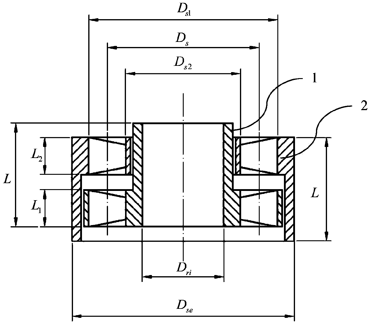
[0030] Please refer to Figure 1 to Figure 10 , figure 1 It is a schematic diagram of a two-dimensional plane structure of an embodiment of a point projection wedge-shaped blade braking stage stator-rotor assembly of the present invention (a specific point is the intersection point of the equivalent meridian plane and the axis of the stator or rotor when the specific poi...


PUM


Abstract

The invention provides a point-projection wedge-shaped blade brake-stage stator and rotor assembly. Stator blades and rotor blades are in a wedge shape with the width gradually increasing from top to bottom and from blade bottom to blade top. The multiple stator blades are circumferentially arranged between the outer wall of a stator leaf crown and the inner wall of a stator body in an inclined mode. The multiple rotor blades are circumferentially arranged between the outer wall of a rotor body and the inner wall of a rotor leaf crown in an inclined mode. The stator blades and the rotor blades are the same in inclining angle and inclining direction. Both the stator blades and the rotor blades are formed through point projection. The point-projection wedge-shaped blade brake-stage stator and rotor assembly is small in hydraulic loss and large in braking torque; after a certain number of point-projection wedge-shaped blade brake-stage stators and rotors and a certain number of turbine-stage stators and rotors are assembled together, working time of a turbine drill can be obviously prolonged, overload capacity of the turbine drill can be obviously improved, stability can be obviously improved when the turbine drill works at a low rotating speed, and the footage during turbine drilling can be obviously increased.

Description

technical field [0001] The invention relates to downhole turbine drilling tools for drilling in the fields of oil, natural gas, coal bed methane, shale gas exploitation, etc. A rotor assembly belongs to the technical field of mechanical manufacturing. Background technique [0002] The turbodrill is the earliest downhole hydraulic motor in industrial application. Its function is to convert the hydraulic pressure energy of the working fluid into mechanical energy, and drive the drill bit to rotate to break the bottom rock. Turbine drilling tool is a kind of downhole dynamic drilling tool commonly used in oil fields. Because the speed of the turbodrill consisting of the existing multi-stage turbine stator-rotor assembly is too high, the drill bit bearings or teeth wear too fast, and the drilling footage and pure drilling time of one trip are much lower than those of rotary table drilling. [0003] In view of the shortcomings of the above-mentioned existing turbine drilling te...

Claims


Application Information

Patent Timeline
Patent Type & Authority Applications(China)
IPC IPC(8): F03B3/00F03B3/12F03B3/18F03B3/16F03B13/02E21B4/02
CPCY02E10/223Y02E10/20
Inventor 谭春飞
Owner CHINA UNIV OF PETROLEUM (BEIJING)
Why Eureka
Try Eureka