Chemical additive mixing pump for nuclear power station

A technology of chemical additives and mixing pumps, which is applied to components, pumps, and pump components of elastic fluid pumping devices, and can solve problems such as complex assembly, mechanical seal end face damage, and no mechanical seal vent hole. To achieve the effect of long-term operation extension, shortening axial dimension and best sealing effect

Active Publication Date: 2011-08-10
SHANGHAI APOLLO MACHINERY
View PDF7 Cites 8 Cited by
  • Summary
  • Abstract
  • Description
  • Claims
  • Application Information

AI Technical Summary

Problems solved by technology

[0005]1. The water absorption chamber of the pump body is a section of straight pipe, and the hydraulic loss is relatively large. The hydraulic velocity field at the impeller inlet is not uniform enough, which will reduce the efficiency of the pump ;
[0006]2. The locking structure of the impeller is that the shaft end of the pump shaft protrudes from the perforation of the impeller hub, and the inner thread of the impeller nut and the outer thread of the impeller end of the pump shaft The thread cooperates to lock the impeller. This locking structure makes the shaft diameter of the pump shaft limited by the hub of the impeller, and then the size of the key and bearing on the pump shaft is also limited. The torque transmitted by the key is small, and the load capacity of the bearing is limited. , so that the safety and reliability of the pump during work are not high enough; in addition, the position of the impeller nut is relatively prominent, completely entering the suction chamber of the pump body, and the volume is also relatively large, and the protruding distance is long, which will stir the water flow at the impeller inlet. Has a certain influence on the hydraulic performance of the impeller inlet
[0007]3. The main seal of the pump body and the pump cover adopts the structure of the O-ring seal, which cannot effectively seal the sealing surface of the pump body and the pump cover due to machining The resulting processing texture;
[0008]4. The whole installation structure adopts to first fix the pump cover on the pump body through studs, and then fix the bearing body support on the pump cover through studs, thus causing The axial dimension of the whole pump is relatively large;
[0009]5. The shaft sleeve in the mechanical seal of the pump cover is next to the impeller, so that the cooperation between the shaft sleeve, the impeller and the shaft is prone to dimensional interference;
[0010]6. There is no mechanical seal vent hole on the pump cover, which cannot effectively discharge the gas at the mechanical seal, so that the air bubbles will damage the sealing end face of the mechanical seal, and due to the transportation Due to the characteristics of the medium, if the air in the mechanical seal chamber of the pump is not emptied, it will cause the crystallization of the medium and cause the mechanical seal to fail;
[0011]7. The bearing seal adopts ordinary skeleton oil seal. When the spring force in the skeleton oil seal is too large, it is easy to cause the phenomenon of shaft holding, which will cause friction between the skeleton oil seal and the pump shaft, resulting in The pump shaft heats up, and when the spring force is insufficient, the gap between the skeleton oil seal and the pump shaft will be too large, causing the lubricating oil to leak;
[0012]8. The bearing body is composed of an intermediate bracket and a bearing bracket and is connected by bolts. During manufacturing, the intermediate bracket and the bearing bracket are processed separately, and the coaxiality of each part Can not be absolutely consistent, high precision requirements for processing and manufacturing, and more complicated assembly

Method used


Image

  • Chemical additive mixing pump for nuclear power station
  • Chemical additive mixing pump for nuclear power station
  • Chemical additive mixing pump for nuclear power station

Examples


Embodiment Construction

[0024] In order to better understand the technical solution of the present invention, it will be described in detail below through specific embodiments in conjunction with the accompanying drawings:

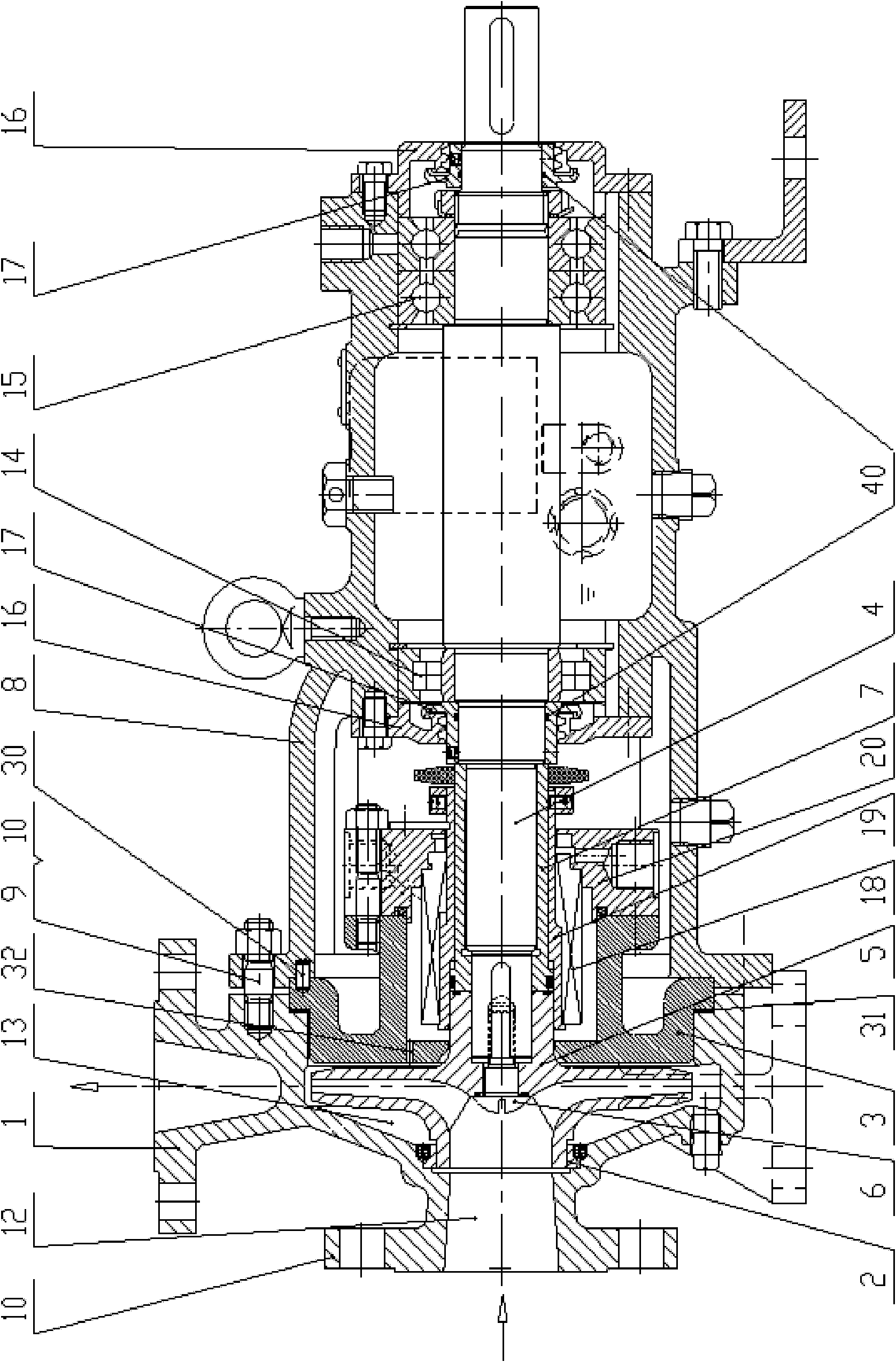
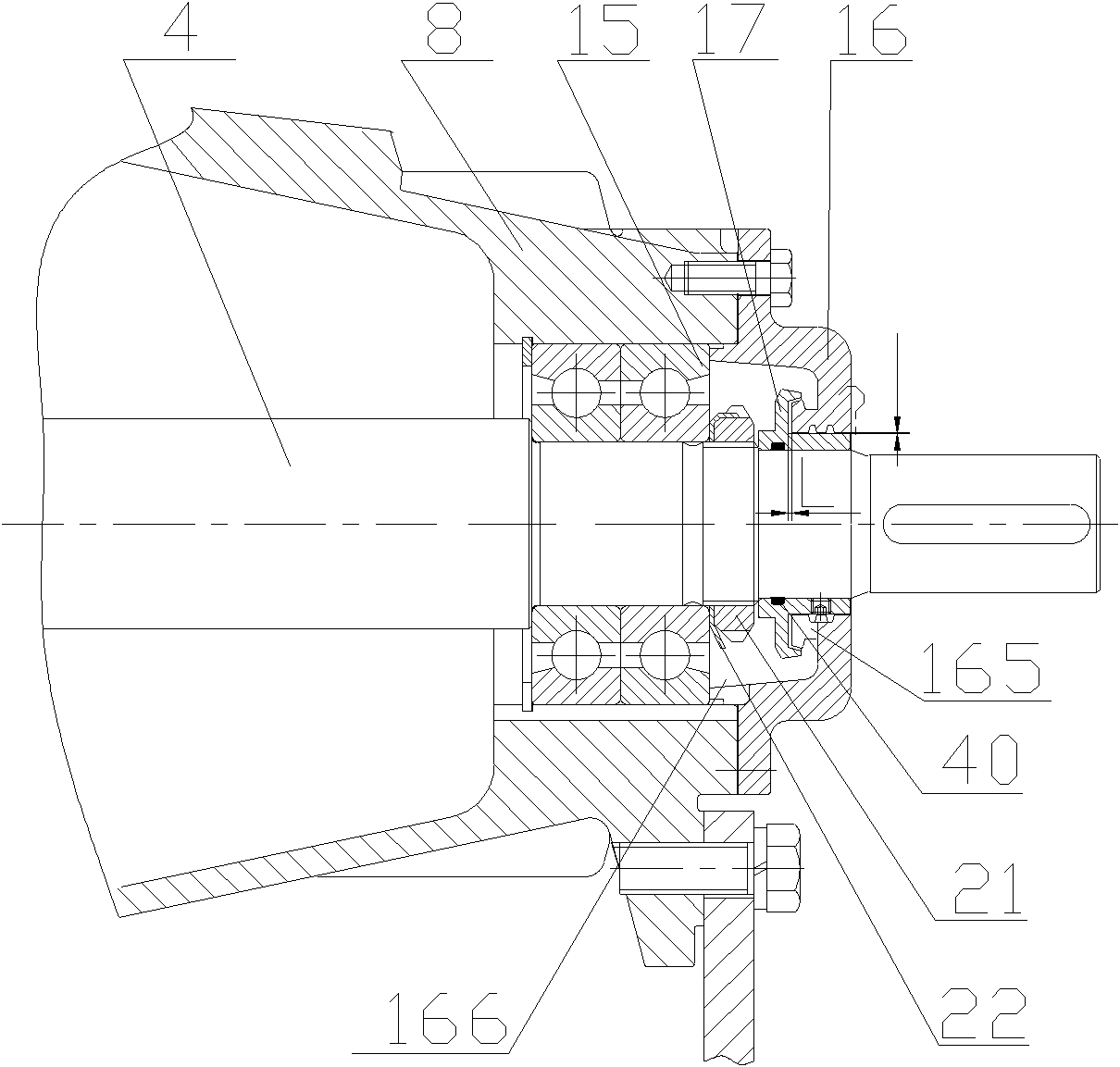
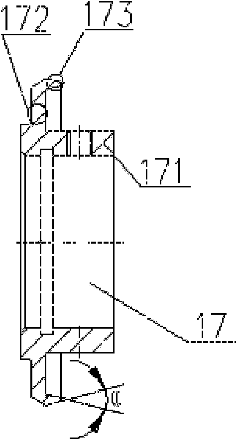
[0025] see figure 1 , the chemical additive mixing pump used in nuclear power plants of the present invention includes a stator assembly, a rotor assembly, a bearing assembly and a shaft seal assembly. The stator assembly includes a pump body 1, a pump cover 3 with a mechanical seal chamber and a pump body seal ring 2; the rotor assembly includes a pump shaft 4, an impeller 5 and a shaft sleeve 7; the bearing assembly includes a Bearing body 8, bearing, two oil retaining pans 17 and two bearing end covers 16; the shaft seal assembly includes a mechanical seal device 18 and a bearing oil seal device, wherein:

[0026] The pump body 1 includes a horizontally arranged inlet flange 11, a water absorption chamber 12 and a volute 13. The water absorption chamber 12 is tapered from lar...


PUM


Abstract

The invention discloses a chemical additive mixing pump for a nuclear power station, which adopts a straight tapered water-absorbing room to lead liquid to flow in a straight tapered contraction pipe, thereby ensuring that the flow velocity is gradually increased, the distribution is uniform, the hydraulic loss is small, and a uniform velocity field is arranged at an inlet of an impeller; the impeller is matched and locked with a locking structure of a pump shaft through external threads of a special locking bolt and internal threads at the shaft end of the pump shaft; the spherical surface of the locking bolt completely conforms to the hydraulic shape of the impeller, so that the locking bolt is integrated with the streamline shape of the impeller into a whole after being installed, thereby maximally ensuring that the inlet water flow of the impeller is not affected; meanwhile, the diameter of the pump shaft and the specification of a bearing can be increased; the larger bearing can be prolonged in service life and also can bear larger load; a pump body is connected with a pump cover in such a manner that the pump cover is directly pressed between the pump body and a bearing body to shorten the overall axial dimension of the pump; and a bearing oil sealing device achieves the ideal sealing effect by adopting the labyrinth sealing, so that no leakage of lubricating oil exists in the endurance test of 400 hours.

Description

technical field [0001] The invention relates to a pump, in particular to a chemical additive mixing pump used in nuclear power plants. Background technique [0002] The safety level of the chemical additive mixing pump is RCC-P3 (nuclear level 3), the manufacturing level is RCC-M3, it belongs to the EAS system (containment spray system), and it is located in the fuel building of the nuclear island of the nuclear power plant. [0003] During the normal operation of the nuclear power plant, the chemical additive mixing pump runs intermittently for 20 minutes every 8 hours to homogenize the NaOH solution in the chemical addition tank; part of the flow is used to prevent the injector suction pipe submerged in the NaOH solution from clogging. [0004] The existing chemical additive mixing pumps used in nuclear power plants have the following defects: [0005] 1. The water absorption chamber of the pump body is a straight pipe type, the hydraulic loss is relatively large, and the...

Claims


Application Information

Patent Timeline
Patent Type & Authority Applications(China)
IPC IPC(8): F04D29/42F04D29/046F04D29/08
Inventor 陆金琪
Owner SHANGHAI APOLLO MACHINERY
Why Eureka
Try Eureka