Method for designing centrifugal impeller splitter blade

A splitter vane and design method technology, applied to components of pumping devices for elastic fluids, mechanical equipment, non-variable pumps, etc., can solve the two halves that cannot be equal, lack of theoretical support, and splitter vane structural form Insufficient design methods and other problems, to achieve the effect of increasing head and efficiency, reducing hydraulic loss, and improving velocity distribution

Inactive Publication Date: 2016-09-28
JIANGSU UNIV
View PDF5 Cites 7 Cited by
  • Summary
  • Abstract
  • Description
  • Claims
  • Application Information

AI Technical Summary

Problems solved by technology

However, the shape of the bone line of the existing splitter vanes is arc-shaped, the radial section is arc-shaped, and the axial section is cylindrical. In the design process, the length of the splitter vane, the size of the inlet offset angle, the outlet The size of the offset angle is given based on empirical formulas and lacks mature theoretical support; secondly, since the flow channel between two adjacen

Method used


Image

  • Method for designing centrifugal impeller splitter blade
  • Method for designing centrifugal impeller splitter blade
  • Method for designing centrifugal impeller splitter blade

Examples


Embodiment Construction

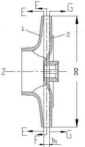
[0018] see figure 1 , the splitter blade 4 in the centrifugal impeller is between two adjacent long blades, the splitter blade 4 is composed of the working surface 5, the back side 6, the inlet side 7, and the outlet side 8, and the working surface 5 is facing the center of the centrifugal impeller The side of the axis Z, the back 6 is the side opposite to the working surface 5 away from the central axis Z, the inlet edge 7 is close to the end of the central axis Z, and the outlet edge 8 is away from the end of the central axis Z.

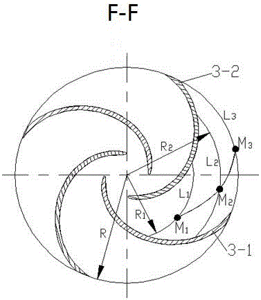
[0019] see figure 2 , The exterior of the centrifugal impeller is composed of a front cover 1 and a rear cover 2, and the splitter blade 4 is located between the front cover 1 and the rear cover 2. In the axial direction of the impeller, the long blades and splitter blades 4 are connected to the front shroud 1 and the rear shroud 2 respectively. In the centrifugal impeller, it is determined that there are three radial cross-sections perpendicula...


PUM


Abstract

The invention discloses a method for designing a centrifugal impeller splitter blade. The method includes the steps that a middle cross section, a front cover plate cross section and a rear cover plate cross section of an impeller are determined; three split flow points on the three cross sections are determined on the three cross sections respectively according to the principle that flows on the two sides of each split flow point are equal, and three bone lines on the three cross sections are obtained; and the three bone lines are mixed and scanned into a curved surface, the curved surface extends towards a front cover plate and a rear cover plate of the impeller till the curved surface intersects with the front cover plate and the rear cover plate, a work face of the impeller splitter blade is obtained, and the thickness of the work face is increased to obtain the back side of the splitter blade. The designed splitter blade can equally divide water flow in a flow channel between two adjacent long blades into two parts equal in flow, speed distribution at an outlet of the impeller can be effectively improved, hydraulic loss in the impeller is reduced, and the lift and the efficiency of the centrifugal impeller are improved.

Description

technical field [0001] The invention relates to a centrifugal impeller technology applied in fluid machinery, in particular to a design method of a splitter vane in the centrifugal impeller. Background technique [0002] Centrifugal impellers are the most widely used impellers in fluid machinery, such as centrifugal pumps, centrifugal fans, centrifugal refrigeration compressors, etc., are all centrifugal impellers. The blades of the centrifugal impeller are composed of long blades and splitter blades. The splitter blades are arranged between two adjacent long blades. Adding splitter blades (that is, short blades) between two adjacent long blades has the following important significance: splitter blades It can not only wash away the wake, effectively prevent the generation and development of the wake, effectively prevent the separation and shedding of the fluid on the negative pressure surface of the long blade (the back of the long blade), but also reduce the displacement co...

Claims


Application Information

Patent Timeline
IPC IPC(8): F04D29/24F04D29/30
CPCF04D29/242F04D29/30
Inventor 赵斌娟张成虎赵尤飞
Owner JIANGSU UNIV
Why Eureka
Try Eureka