Improved winding-machine for rolled or drawn wire/rod

A technology for coilers and bars, applied in the field of coilers, can solve problems such as obstruction of transportation, irregular coils, wire clogging, etc., and achieve the effect of reducing the risk of clogging

Inactive Publication Date: 2009-01-14
SIMAC
View PDF7 Cites 0 Cited by
  • Summary
  • Abstract
  • Description
  • Claims
  • Application Information

AI Technical Summary

Problems solved by technology

[0020] For this reason, under unfavorable or particularly extreme conditions, the wire overlaps, rather than slides on the underlying winding layer, making the coil irregular
[0021] Another major inconvenience is that these loops, generally almost perpendicular to the axis of the drum, are involved in the formation of the roll when it is released from the movable outer flange of the drum to take the roll and send it to the strapping machine , the side loops of the roll can loosen and come off the roll, hampering both its transport and its subsequent tying
[0022] Another serious disadvantage of Mannesmann Demag and later WO-0025952 (EP1126935) is that excessive restraint of the wire guides also leads to undesired overlapping of helical turns, especially for large diameters
Another problem is: the high friction caused by creeping between the guide plates, thus having to "off" the wire when the main wire guide is tilted; and the resulting very high wear of the guide frame, which has to be replaced frequently
[0023] However, the risk of wire jamming still exists due to the impact of the wire against said slotted plate shortly before winding

Method used


Image

  • Improved winding-machine for rolled or drawn wire/rod

Examples


Embodiment Construction

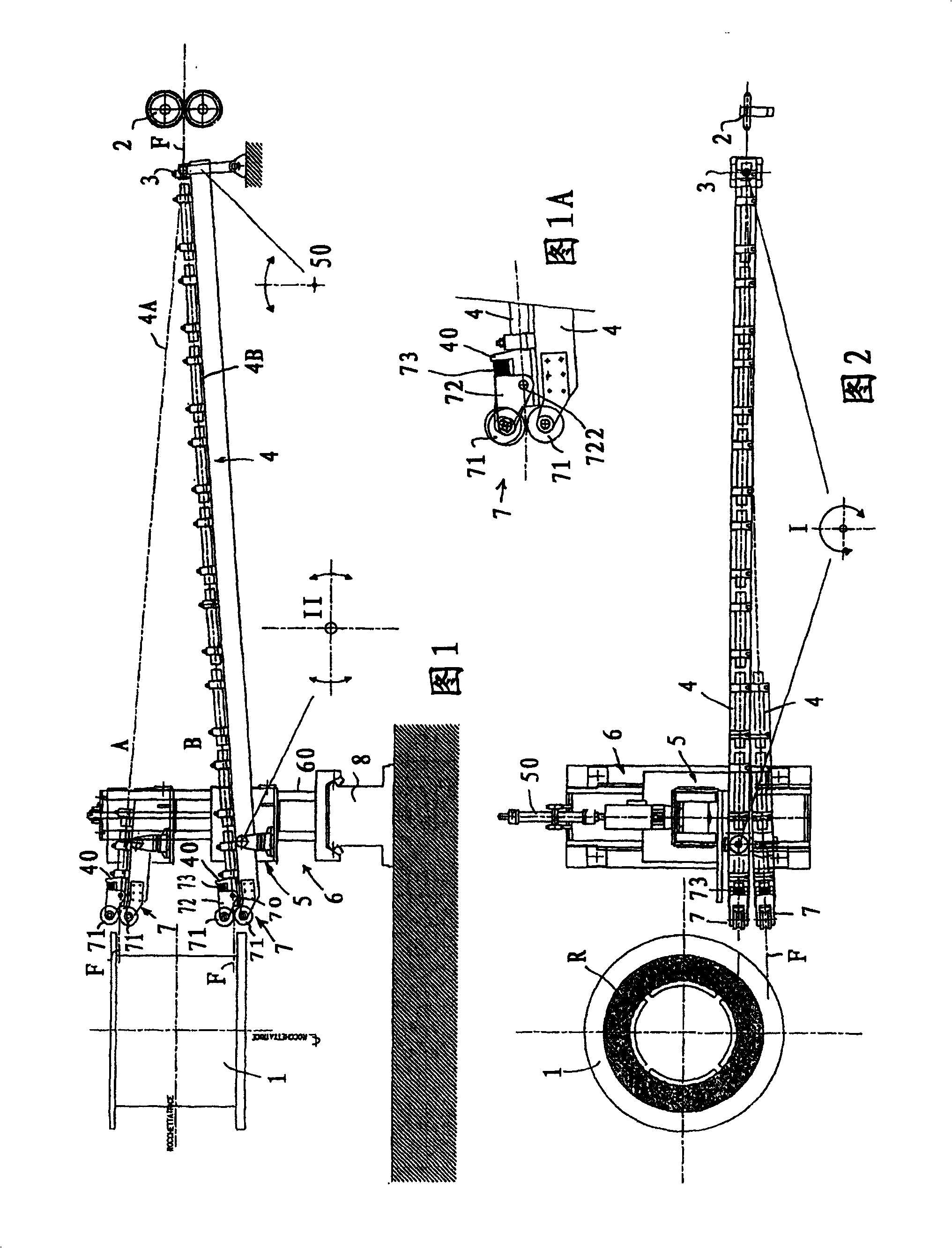
[0037] As disclosed in the above figures, the wire / rod (F) can clearly be seen coming from a prior art rolling mill not represented in the figures (but also from a drawing unit).

[0038] Thereby also upstream the wire / rod cutting means, so that when the coil (R) is complete, the wire / rod can be diverted according to the prior art to another coiler (only one shown), which allows unloading to have been completed roll, which is conveyed to the strapping machine, while another roll is formed.

[0039] Thus schematically, upstream of the individual wire / rod guides (4) there is a feed device, for example with a traction for conveying the wire / rod (F) to the wire / rod guide inlet (3) The device (2), the wire / rod guide inlet (3) is hinged to allow the wire / rod guide to swing back and forth in a vertical plane (4A-4B) to deliver (5-6) helical turns, and with The coiling diameter increases and it oscillates on a horizontal plane (6-8-50) in order to gradually move away from the mandrel...


PUM


Abstract

Winding-machine for rolled or drawn wire / rod (F) with device to form a wire / rod coil (R) in a winding-machine with one or more winding reels (1) placed downstream of a wire / rod working installation, provided with wire / rod-drawing means (2-3) and thereafter: an oscillating wire / rod-guide (4) with wire / rod-guide handling means (6) to lead the end of the wire / rod-guide reel side to follow the winding so that the wire / rod from the said advancing means (2-3) is wound up in the reel (1) with first translation means (6­5) to move the reel side end (1) of the exit opening said wire / rod-guide (4) parallel to the reel / mandrel axis (1) and second translation means (8-6) to move said exit opening of said wire / rod-guide (4) in withdrawal / approach perpendicularly to the axis of said reel / mandrel (1) in order to follow the increase of diameter of the coil (R) during winding-up with improved wire / rod containment system at said exit opening (7). Said wire / rod containment system consists of at least one opposite pair of containment rolls (71) provided at the exit opening (7) of said wire / rod-guide (4).

Description

technical field [0001] The invention relates to a coiler for coiling rolled or drawn wire / rod. Background technique [0002] A wide variety of coilers for coiling rolled or drawn wire / rod are known. [0003] For example, GB2058703 discloses an automatic coiler with a single wire / rod guide for coiling, which guides towards both sides of the drum during coiling in order to follow the coil during coiling. [0004] More relatedly, DE0821666 describes a coiling system for selectively winding wire / rod in two drums (11, 12 in Figure 8), including for downstream forming of a wire / rod processing device. Device for wire / rod coils provided with wire / rod guides (13 / 14) with wire / rod guide movers (15-13) to guide the wire / rods to the individual drums ( 11, 12), the reels have wire / rod translation means (17) to move the end of the wire / rod guide approximately parallel to the axis of the reel to two positions above each reel (11-12). side roll (13). [0005] More relevant for the purpo...

Claims


Application Information

Patent Timeline
Patent Type & Authority Patents(China)
IPC IPC(8): B21C47/12
CPCB21C47/12
Inventor F·卡斯泰拉尼
Owner SIMAC
Why Eureka
Try Eureka