Production device for preventing scratch of pull ring material, and detection method thereof

Active Publication Date: 2019-02-05
山东龙口三元铝材有限公司 +1
View PDF4 Cites 0 Cited by
  • Summary
  • Abstract
  • Description
  • Claims
  • Application Information

AI Technical Summary

Problems solved by technology

[0003] The embodiment of the present invention provides a production device and detection method for anti-scratch pull ring materials, the purpose of which is to prevent scratches on the surface of pull ring materials easily caused by friction with rollers in the existing automatic production line for pull ring materials, and cannot damage the pull ring. Simultaneous tracking and detection of surface defects of ring materials to improve the problem of increasing defective products

Method used


Image

  • Production device for preventing scratch of pull ring material, and detection method thereof
  • Production device for preventing scratch of pull ring material, and detection method thereof
  • Production device for preventing scratch of pull ring material, and detection method thereof

Examples


Embodiment 1

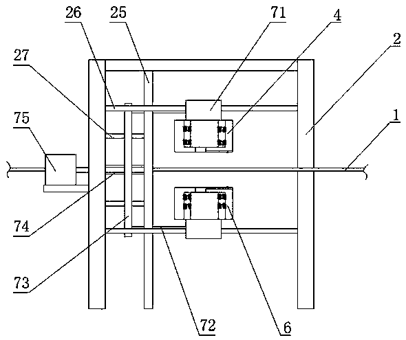
[0064] Such as Figure 8 and Figure 9 As shown, the upper photographing device 4 and the lower photographing device 6 are fixedly installed on the rack 51 through the connecting part, and the two ends of the rack 51 are respectively fixedly connected with a moving rod A54 and a moving rod B55, and the moving rod A54 and the moving rod B55 are slidably mounted on the bracket A2, spanning the whole bracket A2; also include a gear 52 engaged with the rack 51, one end of the gear 52 is connected to the bracket A2, and its input shaft It is driven by a driving device A53, which can be a conventional power device such as an engine or a motor. The length of the rack 51 is determined by the moving speed of the belt-shaped pull-ring material, the width of the belt-shaped pull-ring material, and the angle β between the bracket A2 and the belt-shaped pull-ring material. The driving device of the lower camera 6 is the same as that of the upper camera 4 . In this solution, the upper an...

Embodiment 2

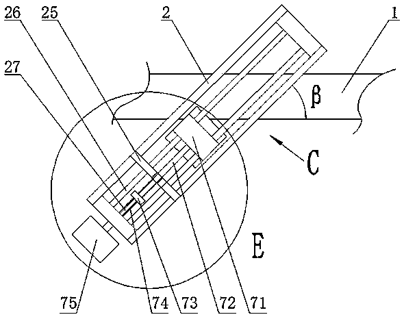
[0067] Such as Figure 10 to Figure 12 As shown, it is another solution of the sliding device 5 of the present application. The upper shooting device 4 is slidably connected to the horizontal sliding bar 26 on the bracket A through the connecting part 71, and can slide along the sliding bar 26. The sliding bar 26 is provided with at least two to ensure that the upper shooting device 4 slides smoothly. balance. A connecting rod 72 is connected to the side of the connecting part 71, and the other end of the connecting rod 72 is fixed on the sliding part 73. The middle part of the sliding part 73 is provided with threads, and its upper and lower ends are respectively provided with sliding holes. On the support A2, a support plate 25 is provided between the left and right side plates, the support plate 25 is vertically arranged, a lead screw 74 is provided between the support plate 25 and the left side plate, and at least two Root slide part slide bar 27. The thread in the midd...


PUM


Abstract

The invention discloses a production device for preventing the scratch of a pull ring material, and a detection method thereof. The production device comprises: a bracket A, a rolling shaft and an unrolling shaft are respectively installed on left and right sides of the bracket A, and a driving device C is connected to one end of the rolling shaft; a plurality of rollers are installed on the bracket A, and two sliding devices are installed on the bracket A; an upper shooting device is installed on the sliding device located above the strip-shaped pull ring material, a lower shooting device isinstalled on the sliding device located below the strip-shaped pull ring material, and camera devices are installed in both of the upper shooting device and the lower shooting device; a positioning sensor is further installed between each camera device and the unrolling shaft, and the camera devices are connected with an image processing system through signal lines; and the production device disclosed by the invention can improve the problems that the surface of the pull ring material is easy to generate friction with the rollers to be scratched in the existing automatic production line of thepull ring material, and that synchronous tracking detection cannot be performed on the defects on the surface of the pull ring material, resulting in increased defective products.

Description

technical field [0001] The invention belongs to the field of aluminum product production, and mainly relates to a production device of an anti-scratch pull ring material and a detection method thereof. Background technique [0002] In the existing automatic production line of pull ring materials, the method of continuously feeding the ring pull material coils to the production line is generally adopted, and then the pull ring materials are subjected to coating, laser and other processing procedures during the operation of the pull ring materials, so as to realize the pulling effect. Automated production of ring materials. During operation, the pull ring material will be in contact with multiple tensioning rollers, and static friction will be generated between these rollers. Due to the fact that the roller itself has a certain moment of inertia and the friction of the roller installation part, etc., the rotation of the roller often lags behind, so that the linear speed of th...

Claims


Application Information

Patent Timeline
Patent Type & Authority Applications(China)
IPC IPC(8): H04N7/18H04N5/232H04N5/235G06K9/00G01N21/89B65H23/26B65H18/10
CPCH04N7/18G01N21/8914B65H18/103B65H23/26B65H2701/19G06V20/20H04N23/60H04N23/743H04N23/73
Inventor 王清山吕鹏
Owner 山东龙口三元铝材有限公司
Why Eureka
Try Eureka