
Buffering material-distribution device of cartridge

A technology of distributing device and silo, which is applied in the field of distributing device of silo, can solve the problem of high crushing rate of block materials, and achieve the effect of solving the effect of high crushing rate of materials

Inactive Publication Date: 2009-01-14
朱耀平
View PDF5 Cites 0 Cited by
  • Summary
  • Abstract
  • Description
  • Claims
  • Application Information

AI Technical Summary

Problems solved by technology

[0005] The purpose of this invention is to provide a buffer distribution device for large silos to solve the problem of high crushing rate of block materials caused by direct feeding

Method used


Image

  • Buffering material-distribution device of cartridge

Examples


Embodiment Construction

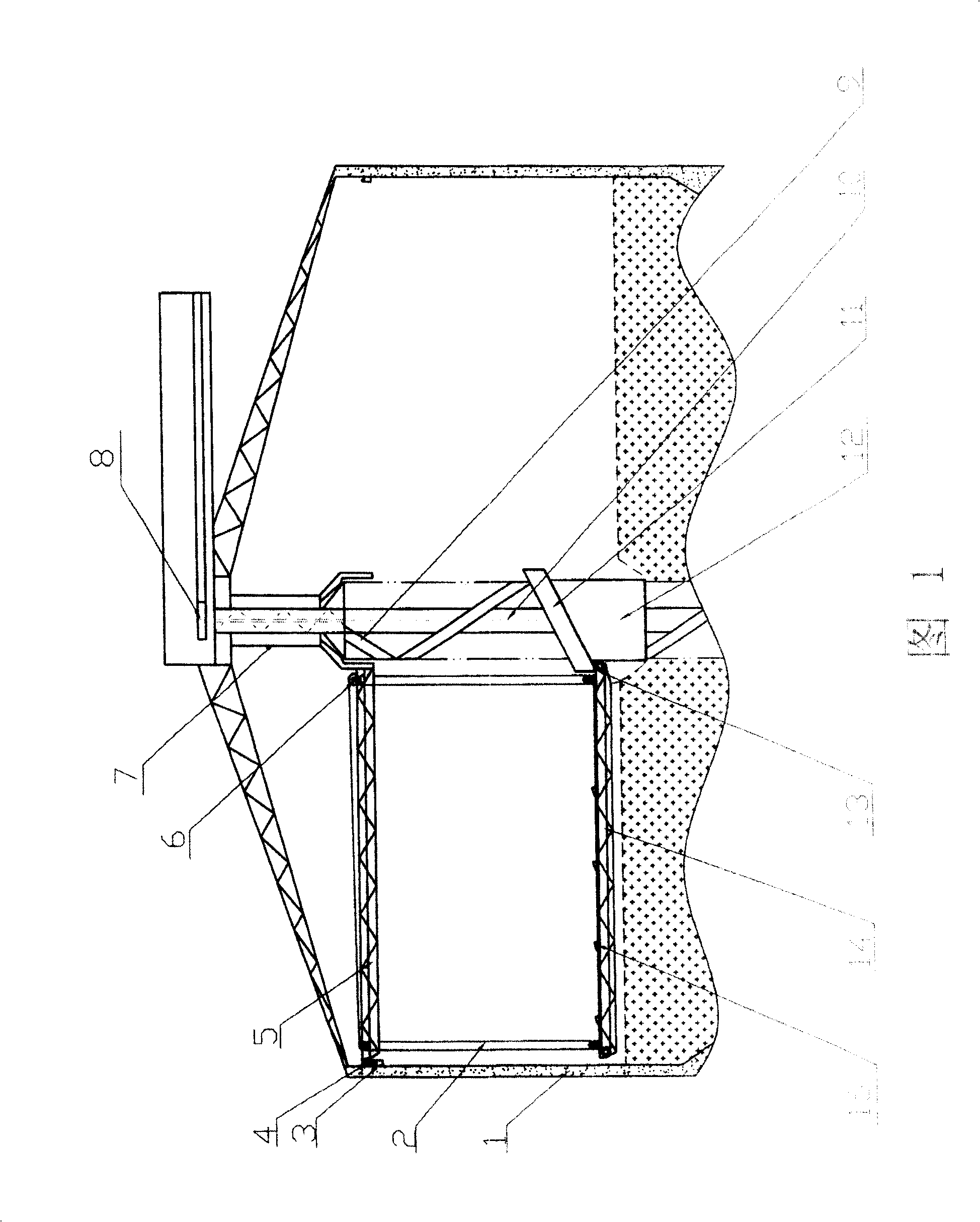
[0018] The structure of the silo buffer distribution device is shown in Figure 1, including a central column 10, a spiral slideway 9, a rotary center 7, a rotary bridge 5, a material distribution rotary bridge 14, a material distribution device 15, a material sealing cylinder 12 and an annular material guide chute 11. The center column 10 is fixed vertically at the center of the silo; the spiral slideway 9 is arranged on the center column 10, the inlet of which communicates with the feed port 8 of the silo, and the outlet directly reaches the bottom of the silo.

[0019] A ring-shaped track 3 is arranged around the upper part of the silo wall 1, and a turning center 7 is arranged in the middle of the silo, which is set on the outside of the central column 10 and the spiral slideway 9; one end of the turning bridge 5 is placed on the ring On the track 3, the other end is fixedly connected with the center of rotation 7, and lies horizontally in the silo. It is driven by the driv...


PUM


Abstract

The invention relates to a buffer distributor of cylinder chamber. Wherein, the chamber has a fixed central post coiled with one or several screw sliding tracks; the inlet of track is through to the inlet of chamber; the upper part of chamber has a rotation bridge rotating around the central post; the lifting distributing rotation bridge via steel line is suspended under the rotation bridge; a sealing cylinder whose upper end is connected to the annular guide incline groove is movably sheathed outside the sliding track, to connect the distributing rotation bridge, therefore, the sealing cylinder can lift with the distributing rotation bridge, and fall back to the material layer of chamber with minimum height. The invention can avoid the block material being broken.

Description

technical field [0001] The invention relates to a silo suitable for storing solid materials, in particular to a distributing device for the silo. The silo distributing device of the present invention is suitable for distributing bulk solid materials. Background technique [0002] A silo is a large-scale device used to store and unload bulk materials conveniently. It is widely used in industrial systems such as coal, electric power, metallurgy, building materials, and grain. [0003] CN 1724318 patent application provides a kind of advanced first-in-first-out silo with floor flat bottom. The silo is provided with an annular rotary chamber and an annular rotary bridge at the bottom of the silo. At this time, the material above the inclination angle in the silo can directly flow into the blanking ring groove naturally, and the material below the inclination angle will be transported to the blanking ring layer by layer from the bottom through the rotation of the circular rotary...

Claims


Application Information

Patent Timeline
Patent Type & Authority Patents(China)
IPC IPC(8): B65D88/54B65G65/32B65G69/16B65G69/04
Inventor 朱耀平
Owner 朱耀平
Learn More