Valve system, especially for improving flow ratio of air inlet valve

A flow ratio, internal combustion engine technology, applied in the direction of internal combustion piston engine, charging system, swing spool valve, etc., can solve the problem of concentricity of the plastic intake pipe, and achieve the effect of light weight, reducing angle error and reducing noise.

Inactive Publication Date: 2009-01-14
SIEMENS AG
View PDF4 Cites 0 Cited by
  • Summary
  • Abstract
  • Description
  • Claims
  • Application Information

AI Technical Summary

Problems solved by technology

In addition, when the intake pipe flange is aligned with the cylinder head by tightening the bolts on the cylinder head, the concentricity of the position in the plastic intake pipe may be deteriorated

Method used


Image

  • Valve system, especially for improving flow ratio of air inlet valve
  • Valve system, especially for improving flow ratio of air inlet valve
  • Valve system, especially for improving flow ratio of air inlet valve

Examples


Embodiment Construction

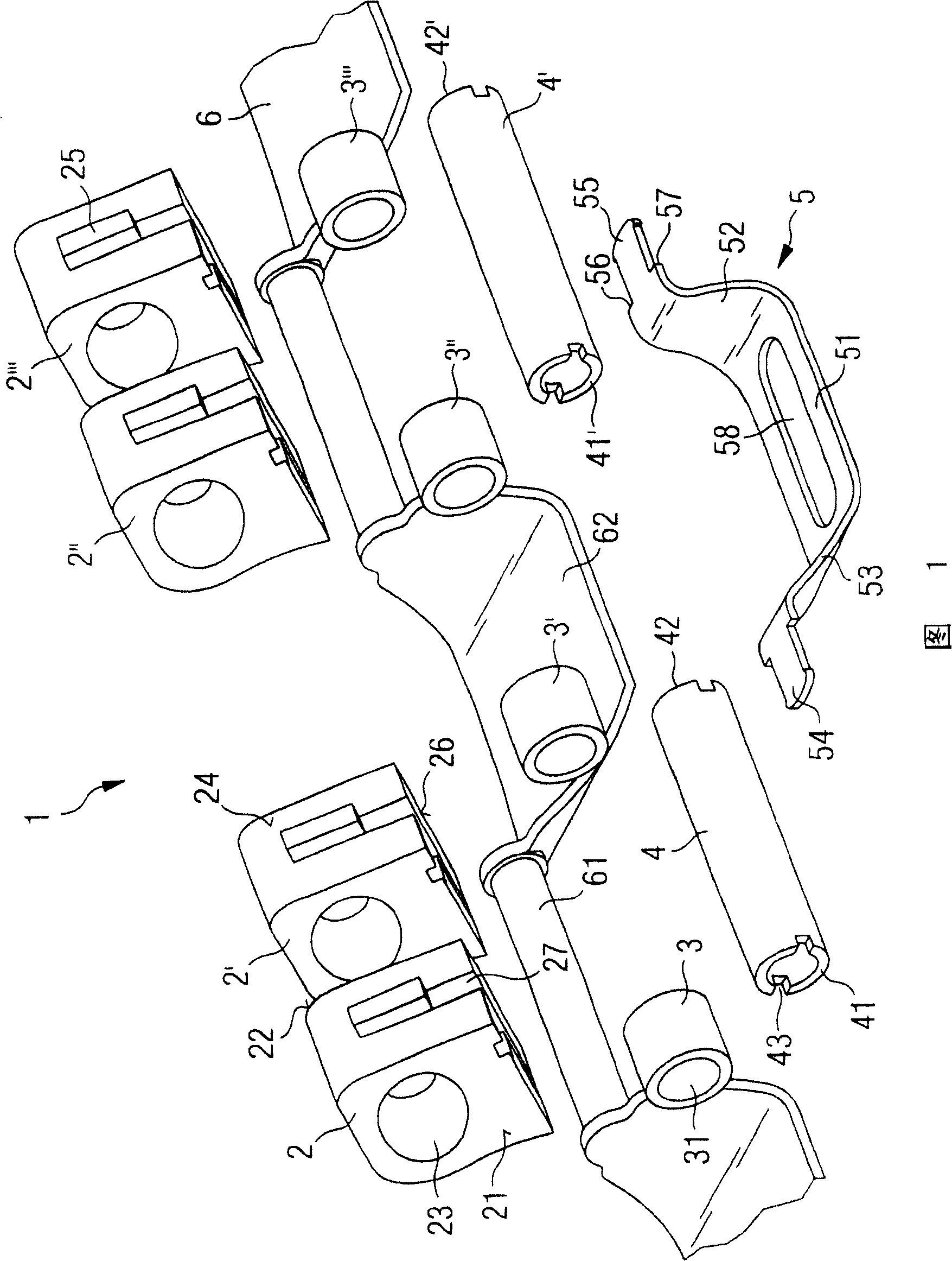
[0017] FIG. 1 shows an exploded view of a valve system 1 according to the invention with four support parts 2, 2', 2", 2"', four bearing bushings 3, 3', 3", 3". ', two hollow shafts 4, 4', a valve 5 and an elastic housing 6 (elastic material). For example, four valves 5 and a corresponding number of other components 2 - 4 and 6 are required for a 4-cylinder engine.

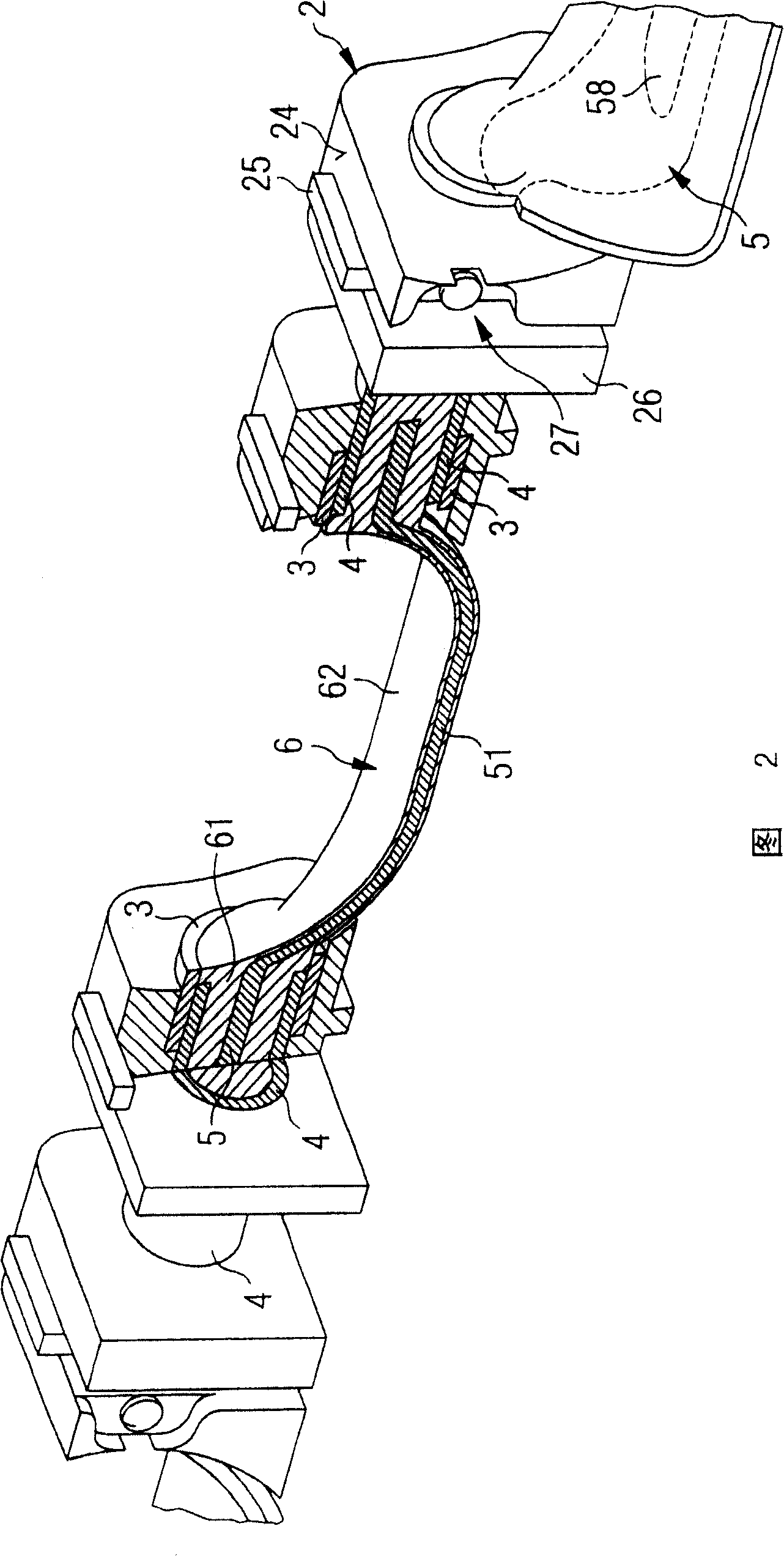
[0018] FIG. 2 likewise shows a valve system according to the invention, the section shown in FIG. 2 passing perpendicularly through the axis of rotation of the valve system 1 . Parts of another valve including components can also be seen on the right side of FIG. 2 .

[0019] A support member 2 is substantially cuboid. A bore 23 passes through the two opposing surfaces 21 and 22 , which bore is suitable for receiving either the bearing sleeve 3 , the hollow shaft 6 or the elastic housing 6 . A third surface 24 has a guide shoulder 25 . This guide shoulder 25 is guided in a groove formed in an intake pipe (not ...


PUM


Abstract

The flap system to control the air intake flow ratios, to internal combustion motor inlet valves, has at least one U-shaped flap (5) with connecting tongues (54,55) at their ends. At least two hollow connection shafts (4) have structured ends to take the tongues in a working fit. At least two bearing blocks (2) have drillings to accommodate the shafts with bearing bushes (3). The flap surface is coated with an elastic material (6) and / or the shafts are filled with it.

Description

technical field [0001] The invention relates to a valve system, in particular for changing the flow ratio on an intake valve. Background technique [0002] Valve systems are used in the intake system of internal combustion engines to influence the air flow, either to change the length of the swivel tube or to change the flow ratio at the intake valve. Many different embodiments of such valve systems are known. For example, there are valve systems in which the valve has its own carrier shaft and drive shaft, which are opened and closed together by a valve drive. There are also valve systems with a penetrating torque drive, which is connected to the shaft section either via a through shaft or via a rigid valve segment connection. If the air flow is not to be disturbed when the valve is to be opened, it is preferred to use a construction with a penetrating torque drive and shaft section. For this purpose it is necessary to avoid shafts and valves located inside the gas flow....

Claims


Application Information

Patent Timeline
Patent Type & Authority Patents(China)
IPC IPC(8): F01L7/10F02D9/10F02B27/02F02B31/06F02D9/02F02D9/16F02M35/10
CPCY02T10/146F02D9/16F02B27/0284F02B31/06F02B27/0215F02M35/10262Y02T10/12
Inventor S·戴斯G·梅内
Owner SIEMENS AG
Why Eureka
Try Eureka