
Developing unit and image forming device having the developing unit

一种显影单元、成像设备的技术,应用在应用电荷图形的电记录工艺的设备、应用电荷图形的电记录工艺、电记录术等方向,能够解决位置关系偏移、显影剂不能均匀移动等问题,达到均匀接触状态的效果

Inactive Publication Date: 2009-01-14
MURATA MASCH LTD
View PDF11 Cites 0 Cited by
  • Summary
  • Abstract
  • Description
  • Claims
  • Application Information

AI Technical Summary

Problems solved by technology

However, since the pressure for the photoconductive drum is applied to the pressure roller, if the positional relationship between the restricting member and the pressure roller is not precisely set, the positional relationship between the photoconductive drum and the developing sleeve is shifted, while developing The agent does not move evenly from the developer sleeve to the photoconductive drum

Method used


Image

  • Developing unit and image forming device having the developing unit
  • Developing unit and image forming device having the developing unit
  • Developing unit and image forming device having the developing unit

Examples


Embodiment Construction

[0056] An embodiment of the present invention is described below. The embodiments to be described below are preferred specific embodiments for realizing the present invention. Therefore, there are various technical limitations in this description. However, the present invention is not limited to these Examples, except as clearly indicated in the following description to limit the present invention.

[0057] (overall structure of imaging device)

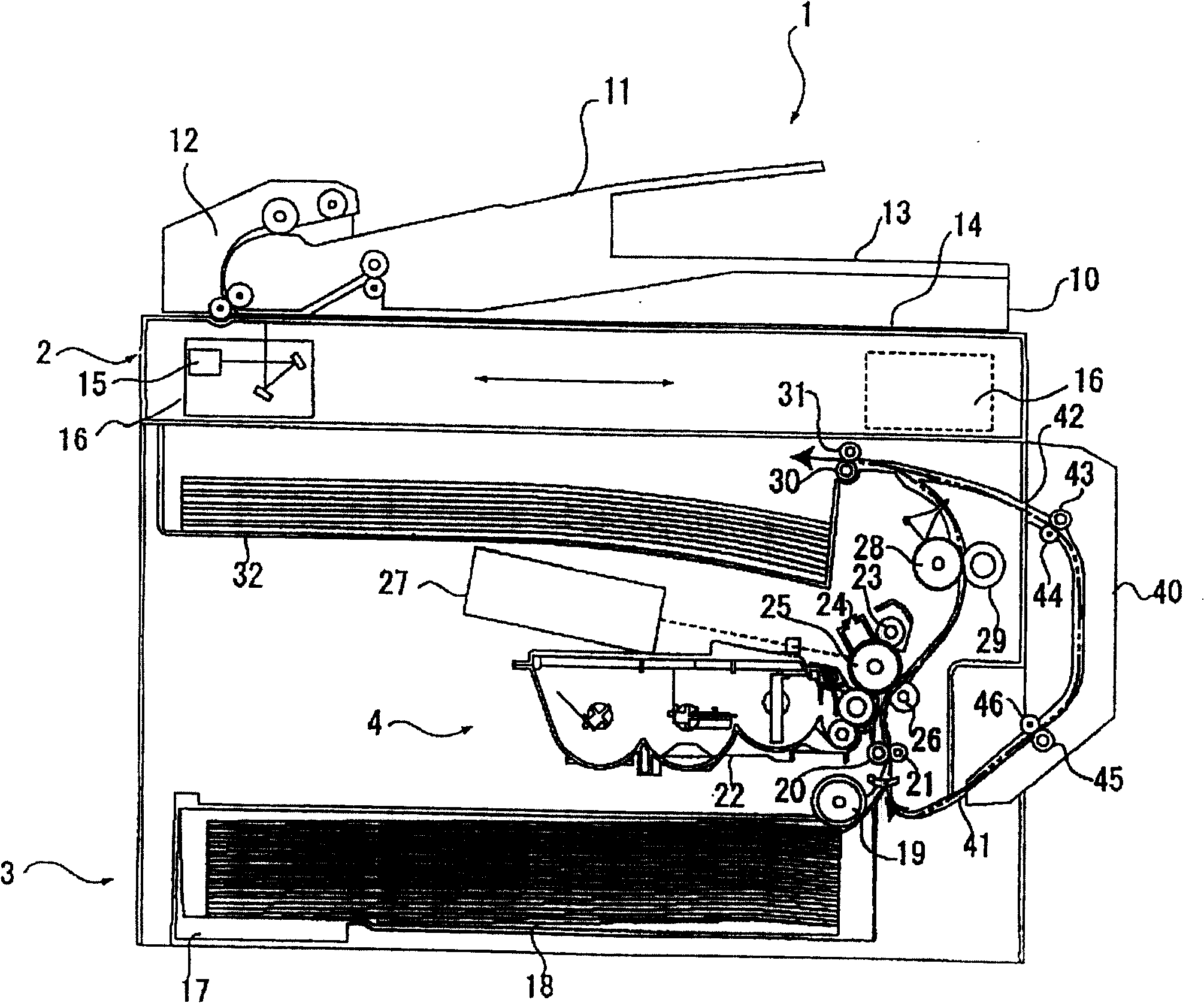
[0058] figure 1 It is a schematic cross-sectional view of the entire imaging device according to an embodiment of the present invention. In the upper part in the image forming apparatus 1, a document scanning unit 2 is provided. In the lower part of the image forming apparatus 1, a paper feeding unit 3 and a printing unit 4 are arranged in order from the bottom surface.

[0059] In the document scanning unit 2 , a document placed on a document tray 11 is conveyed to a scanning position by a document conveying device 12 and discha...


PUM


Abstract

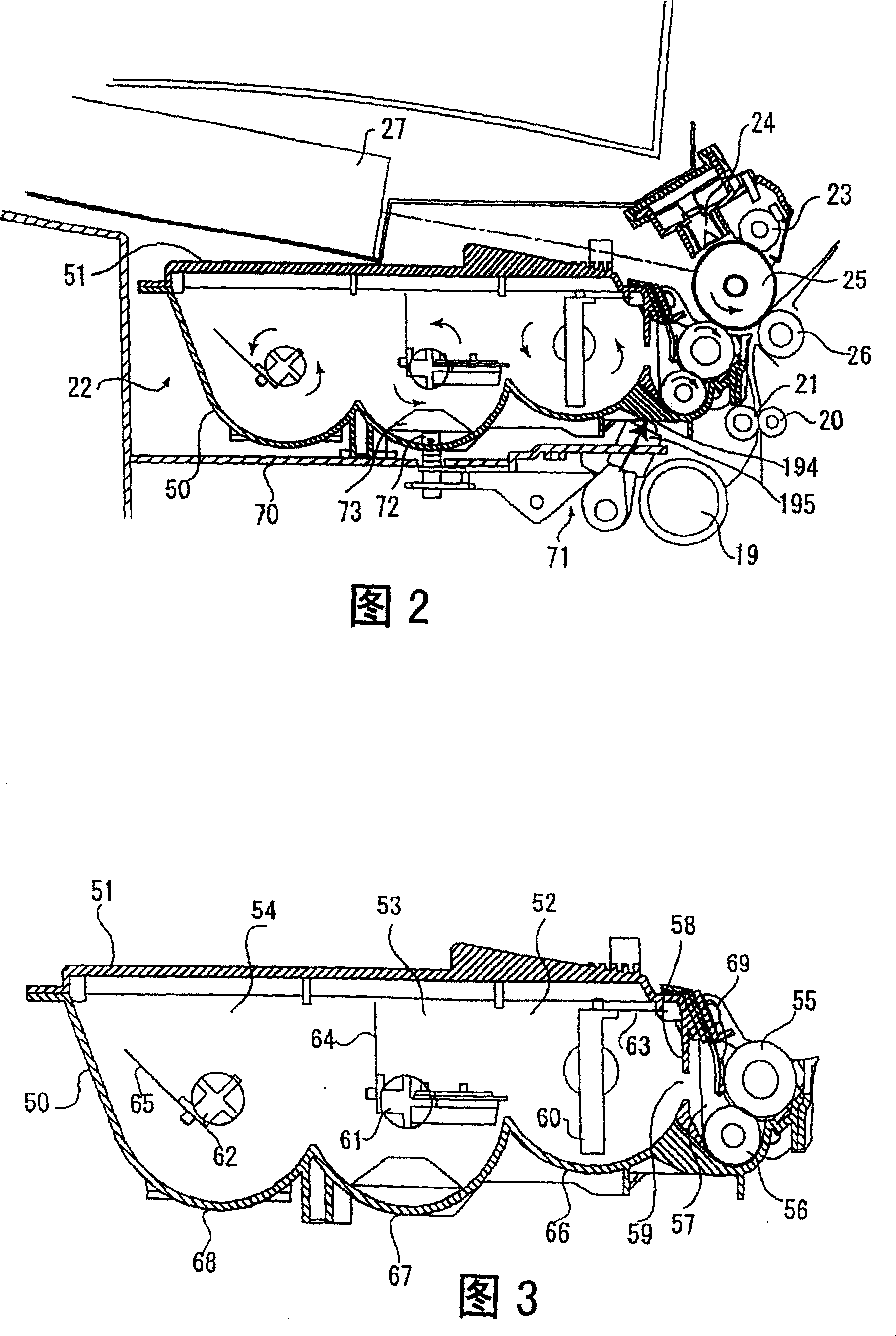
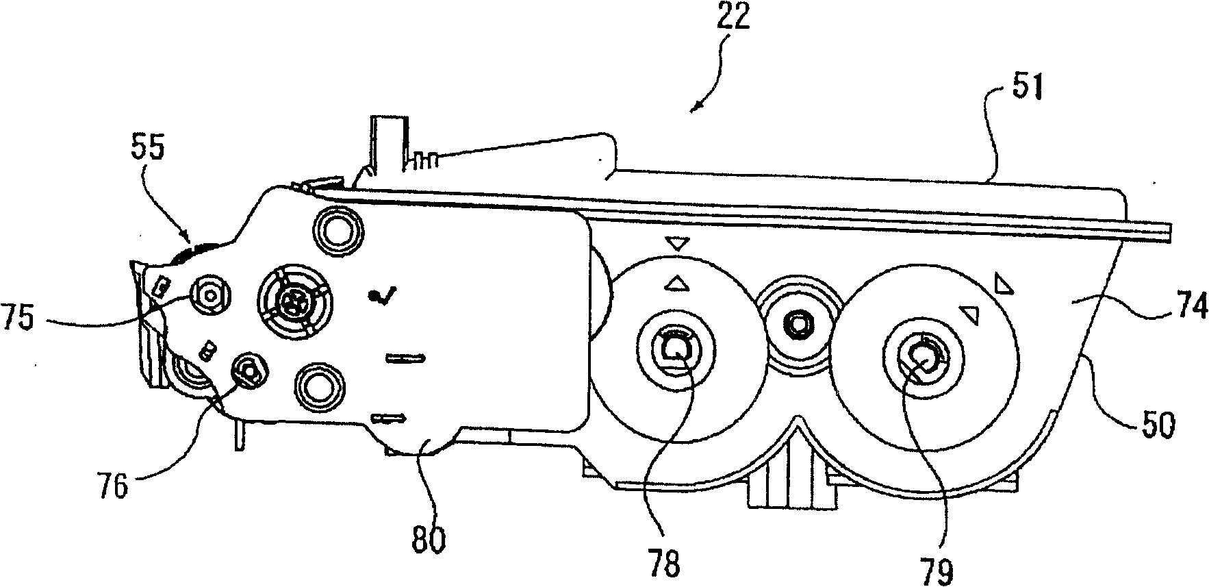
An image forming device includes an electrostatic latent image carrier on which an electrostatic latent image is formed, a main frame which supports the electrostatic latent image carrier and a developing unit. The developing unit includes a developer carrier for supplying a developer to the electrostatic latent image carrier and a replenish chamber for replenishing the developer in the developer carrier. The developing unit is inserted removably in the main frame. A pressing mechanism is provided on the main frame and presses a bottom surface of the developing unit in a pressing direction along a straight line orthogonal to a rotational center shaft of the electrostatic latent image carrier and a rotational center shaft of the developer carrier. The developing unit includes a guide member which is fit into one end part of the rotational shaft of the electrostatic latent image carrier and guides the developing unit to move along the straight line. The main frame includes a positioning long hole which is fit into another end part of the rotational shaft of the developer carrier and guides the developing unit to move along the straight line.

Description

technical field [0001] The present invention relates to a developing unit, which is used in copiers, printers and facsimile machines, for attaching a developer to an electrostatic latent image and developing the electrostatic latent image, and relates to a developing unit having the developing unit imaging equipment. Background technique [0002] In an image forming apparatus, when an image forming process is carried out by attaching a developer (toner) to an electrostatic latent image carrier on which an electrostatic latent image is formed, as the developer is used in the image forming process, the remaining amount of the developer also decrease. Thus, it is necessary to replenish the developer when necessary. Therefore, the developing unit is designed to be insertable and detachable with respect to the image forming apparatus. When necessary, the developing unit is removed from the image forming apparatus, and the developer is replenished, or the developing unit is rep...

Claims


Application Information

Patent Timeline
Patent Type & Authority Patents(China)
IPC IPC(8): G03G15/08G03G15/00G03G21/18
CPCG03G21/1671G03G2221/1654G03G15/0813G03G21/1647G03G2221/163
Inventor 河合秀明
Owner MURATA MASCH LTD
Learn More