Vortex cold medium coiler and fin-free condenser

A type of condenser and scroll technology, applied in evaporators/condensers, refrigerators, refrigeration components, etc., can solve problems such as refrigerant leakage, waste, and inability to remove scale, to eliminate pressure drop, save manufacturing costs, and eliminate Effect of Weld Leakage

Inactive Publication Date: 2009-01-21
吕学能
View PDF13 Cites 0 Cited by
  • Summary
  • Abstract
  • Description
  • Claims
  • Application Information

AI Technical Summary

Problems solved by technology

Secondly, a large group of welding seams 76 of many U-shaped joints 74 will inevitably have one or two outer weak points (weak points). This weak point is flawless when tested, but after a period of use, or due to vibration, or due to Corrosion, resulting in refrigerant leakage
This kind of situation is not uncommon, and a large group of fins can cause the scale accumulation between the gaps and the crossing of the coil to be difficult to remove, and the consequences are even more serious
[0003] In addition, since the refrigerant coil groups in the conventional condenser all form a cuboid, the airflow provided by at least one fan is a hollow cone, such as figure 2 As shown, when the hollow conical wind section 90 blown by the fan is blown to a rectangular refrigerant coil unit 70, it will produce: 1. There is no wind at the center 702; 2. There is no wind at the four corners 704; 3. The wind at the wind section 90 Zone 902 and wind zone 904 blow to the space outside the refrigerant coil unit 70, completely wasting

Method used


Image

  • Vortex cold medium coiler and fin-free condenser
  • Vortex cold medium coiler and fin-free condenser
  • Vortex cold medium coiler and fin-free condenser

Examples


Embodiment

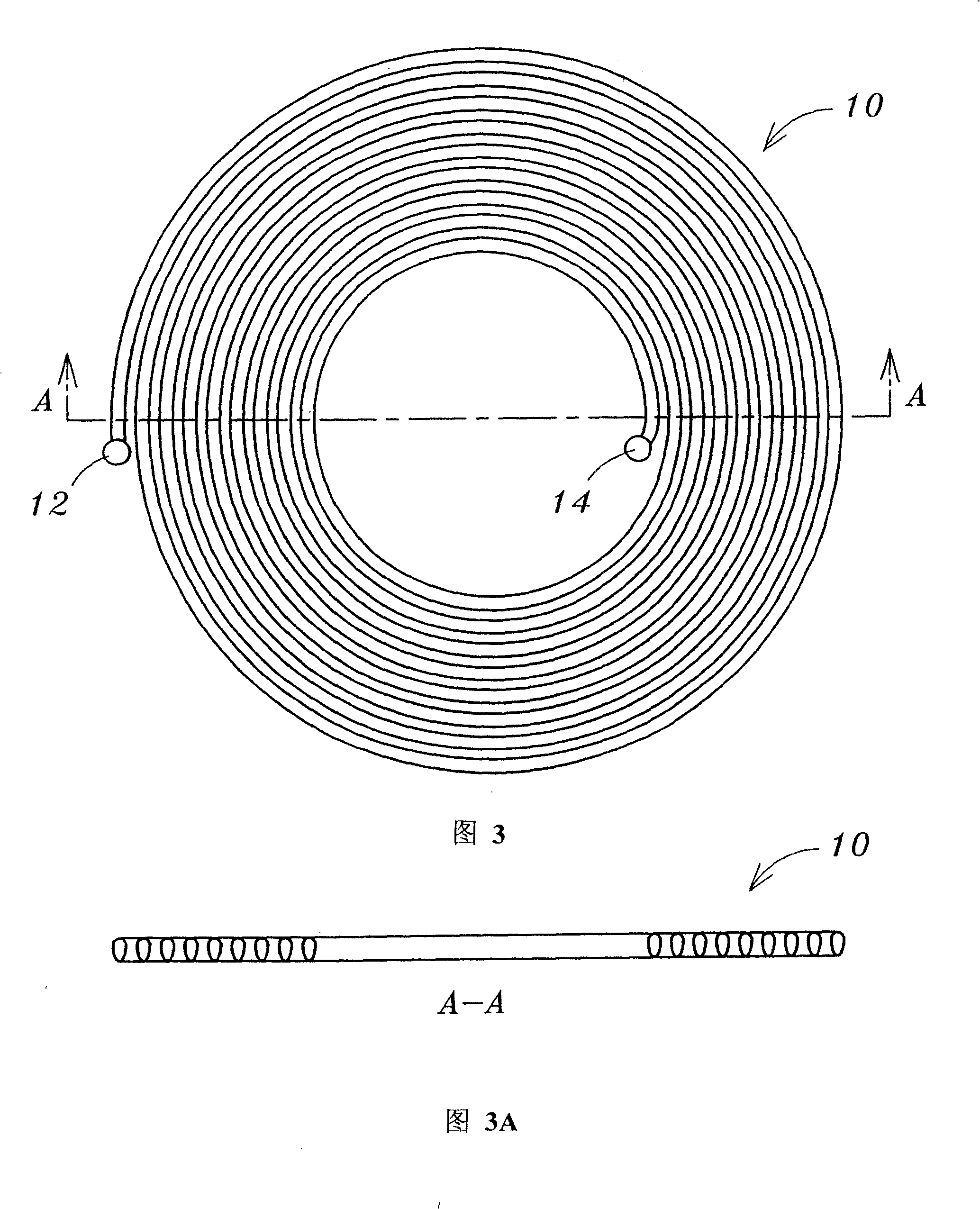
[0047] Embodiment: Please refer to Fig. 3, which is one of the preferred embodiments of the present invention, a flat spiral type refrigerant coil 10 (hereinafter referred to as "refrigerant coil 10") formed by coiling streamlined section tubes. ”) as the basis, its peripheral inlet end is connected to a distribution pipe 12, and the vapor refrigerant enters the refrigerant coil 10 through the distribution pipe 12, and its inner outlet is connected to a collection pipe 14 to collect the liquefied liquid refrigerant . This embodiment takes a streamlined section pipe as an example, but those familiar with the field of the present invention should understand that the scope of this case is not limited thereto.

[0048] FIG. 4 is a cross-sectional view of a group of coils 100 formed by a plurality of layers of refrigerant coils 10 and 10'. Among the refrigerant coils 10 in odd layers, the gaseous refrigerant inlet distribution pipe 12 is located on the outside of the left side of ...


PUM


Abstract

The present invention relates to spiral-curved medium coil and condenser, and is especially one kind of evaporating medium condenser without fin for the outdoor unit in refrigerating system. The new integral spiral curved medium coil structure of metal pipe in streamlined cross section is superior to traditional parallel tube bundle plus U-shaped union structure, which possesses complicated welding operation, likely leakage, increased pressure drop and excessive power consumption, and has raised EER value.

Description

technical field [0001] The invention relates to a refrigerant coil and a finless condenser, in particular to a spiral refrigerant coil and a condenser using the spiral refrigerant coil. Background technique [0002] Generally, the structure of the refrigerant coil in the conventional refrigerant condenser is the same regardless of whether the metal tube it uses is a circular tube or an oval tube, and no matter whether the cooling method it uses is air-cooled or water-cooled, such as figure 1 As shown, its refrigerant coil group 70 is composed of a group of straight tubes 72 of considerable length, which pass through a group of fins 80 in parallel in the same direction, and are respectively fixed on two opposite support plates 82 with their two ends, and then a group of metal The U-shaped joints 74 are respectively welded to the ports of two adjacent straight pipes 72 to connect each group of coils to form a cuboid reciprocating refrigerant coil group 70 . This kind of struc...

Claims


Application Information

Patent Timeline
Patent Type & Authority Patents(China)
IPC IPC(8): F28D5/02F28D1/047F25B39/04
CPCF28D5/02F28D7/028F25B39/04F28F9/013F25B2339/041F28D7/04
Inventor 丁兆元
Owner 吕学能
Why Eureka
Try Eureka