
Double-channel heat exchange dehumidification device

A dual-channel, heat exchanger technology, applied in the direction of household heating, heating mode, household heating, etc., can solve the problems of complex structure and high energy consumption of dehumidification system

Pending Publication Date: 2020-10-27
合肥天鹅制冷科技有限公司
View PDF0 Cites 0 Cited by
  • Summary
  • Abstract
  • Description
  • Claims
  • Application Information

AI Technical Summary

Problems solved by technology

[0006] The purpose of the present invention is to provide a dual-channel heat exchange dehumidification device to solve the problems of complex structure and high energy consumption in the prior art dehumidification system

Method used


Image

  • Double-channel heat exchange dehumidification device

Examples


Embodiment Construction

[0026] The present invention will be further described below in conjunction with the accompanying drawings and embodiments.

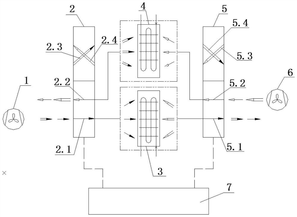
[0027] like figure 1 As shown, a dual-channel heat exchange and dehumidification device includes an internal fan 1, an external fan 6, a first reversing air valve 2, a second reversing air valve 5, a first dehumidification heat exchanger 3, a second dehumidification exchanger The heater 4, the first reversing air valve 2, and the second reversing air valve 5 are all two-position four-way reversing air valves, and the two-position four-way reversing air valve has two sets of normal position passages and two sets of working position passages , the first dehumidification heat exchanger 3 and the second dehumidification heat exchanger 4 respectively have two ventilation sides, the air inlet of the internal fan 1 can be switched to lead to the indoor or outdoor, and the air inlet of the external fan 6 always leads to the outdoor, This results in two workflo...


PUM


Abstract

The invention discloses a double-channel heat exchange dehumidification device. The device comprises an inner fan, an outer fan, a first reversing air valve, a second reversing air valve, a first dehumidification heat exchanger and a second dehumidification heat exchanger, wherein the first reversing air valve and the second reversing air valve are two-position four-way reversing air valves; an air inlet of the inner fan can be switched to communicate with the inside and the outside, and an air inlet of the outer fan always communicate with the outside; and the inner fan is switched to communicate with the inside and the outside, and the first reversing air valve and the second reversing air valve are switched to be in normal state positions and working positions, so that the functions ofventilation, dehumidification, heat extraction and the like are achieved. The double-channel heat exchange dehumidification device has the advantage of being simple in structure, and can greatly reduce energy consumption.

Description

technical field [0001] The invention relates to the field of air-conditioning dehumidification devices, in particular to a dual-channel heat exchange and dehumidification device. Background technique [0002] With the rapid development of special refrigeration equipment, there are more and more environmental protection requirements for special loads and special cabins. For example, it is required to quickly send dry and cold air with temperature and humidity that meet the requirements in high temperature and high humidity environments. Although there are currently There are many solutions, but under the constraints of space, airtightness and energy consumption, there are not many solutions that can be solved efficiently. [0003] At present, dehumidification is a high-energy-consuming task for air-conditioning, and it is also an important technology in air-conditioning. The core component of the advanced and upgraded solid dehumidification technology, because of its simple ...

Claims


Application Information

Patent Timeline
Patent Type & Authority Applications(China)
IPC IPC(8): F24F3/14F24F11/64F24F11/72F24F11/89F24F13/30
CPCF24F3/1405F24F3/1429F24F13/30F24F11/64F24F11/72F24F11/89
Inventor 王伟万士军王建
Owner 合肥天鹅制冷科技有限公司
Learn More