Maintenance timing detection mechanism of brake controlling device for railway vehicle

A technology for a railway vehicle and a control device is applied in the field of a maintenance period detection mechanism using a brake control device, and can solve the problems of low reliability of detection accuracy and the like

Inactive Publication Date: 2009-01-21
NABLESCO CORP
View PDF3 Cites 0 Cited by
  • Summary
  • Abstract
  • Description
  • Claims
  • Application Information

AI Technical Summary

Problems solved by technology

In this way, if the maintenance time is detected based on the comparison with the preset reference value, there is a problem that the reliability of the detection accuracy is low.

Method used


Image

  • Maintenance timing detection mechanism of brake controlling device for railway vehicle
  • Maintenance timing detection mechanism of brake controlling device for railway vehicle
  • Maintenance timing detection mechanism of brake controlling device for railway vehicle

Examples


Embodiment Construction

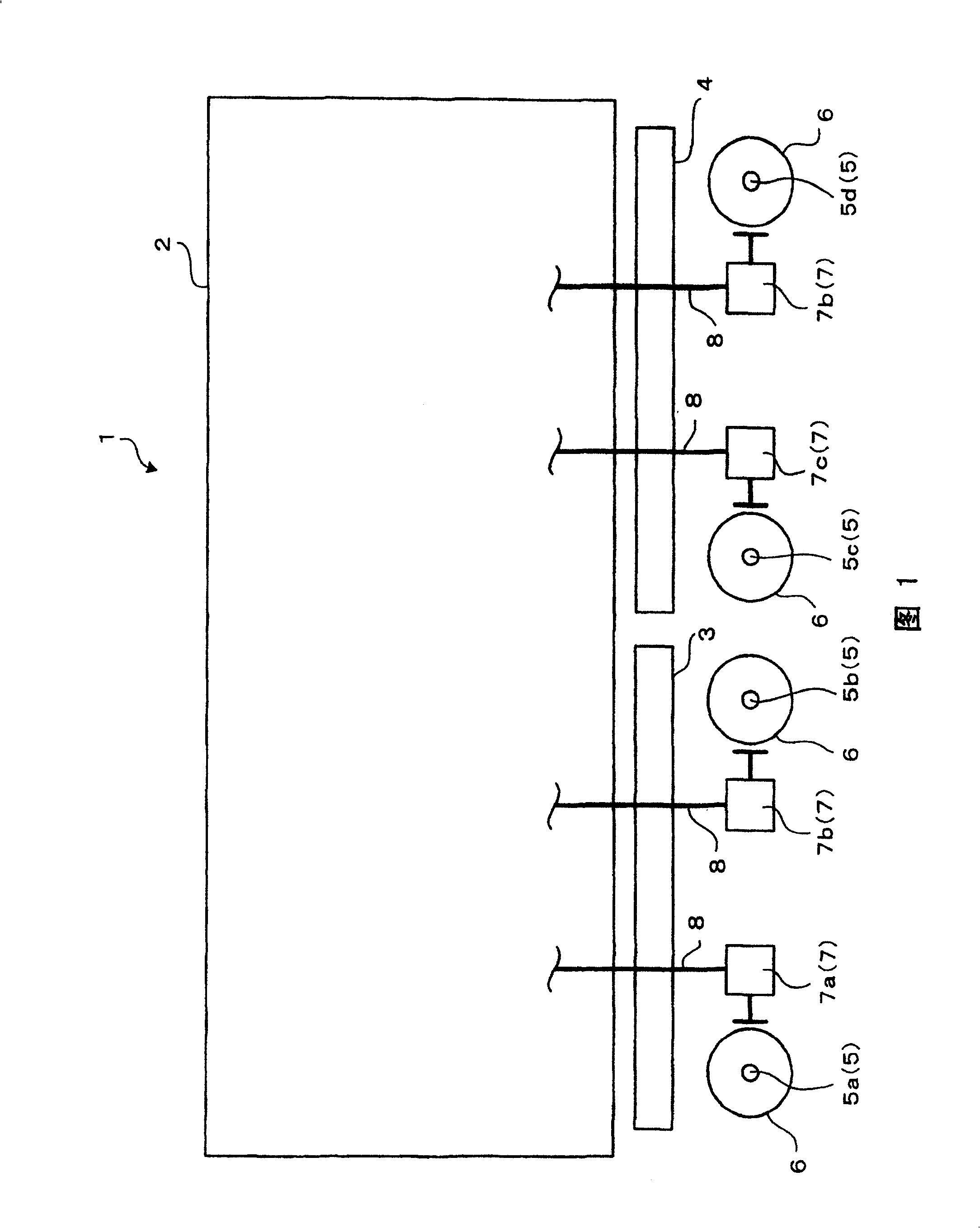
[0033] Next, preferred modes for implementing the present invention will be described with reference to the drawings. FIG. 1 is a schematic diagram illustrating a part of a railway vehicle 1 , and is a diagram for explaining a railway vehicle brake to which a maintenance timing detection mechanism of a railway vehicle brake control device according to an embodiment of the present invention is applied. As shown in FIG. 1, a car body 2 in a railway vehicle 1 is supported by underframes 3-4 provided at the front and rear. Two axles 5 are respectively provided on the chassis 3-4, and two wheels 6 are mounted on the left and right sides (both sides in the direction perpendicular to the drawing) on ​​each axle 5 (5a-5d). Moreover, each brake cylinder 7 (7a-7d) which applies braking force to each axle|axle 5 (5a-5d) is attached to the base frame 3·4. The brake cylinder 7 applies a braking force to the axle 5 by actuating a brake shoe in contact with the wheel 6 or a brake shoe in co...


PUM


Abstract

To improve detection accuracy of maintenance timing by restraining detection error of the maintenance timing according to actuation environment and conditions at the time of actuating a brake. This mechanism comprises a first brake cylinder pressure detector 19a detecting first brake cylinder pressure of a first brake cylinder 7a, a second brake cylinder detector 19b detecting second brake cylinder pressure of a second brake cylinder 7b, and a judging part 34a, into which signals detected by the first brake cylinder pressure detector 19a and the second brake cylinder pressure detector 19b are inputted. The judging part 34a detects the maintenance timing and transmits maintenance signals based on the signals detected by the first brake cylinder pressure detector 19a and the second brake cylinder pressure detector 19b when a condition that pressure difference between both of the brake cylinder pressures is beyond a predetermined value occurs predetermined times.

Description

technical field [0001] The present invention relates to a maintenance time detection mechanism of a railway vehicle brake control device for detecting the maintenance time of the railway vehicle brake control device in the railway vehicle brake control device. The brake cylinder pressure generated by the working fluid (in particular, compressed air) of each brake cylinder that applies braking force to each axle of the railway vehicle is controlled. Background technique [0002] Conventionally, railway vehicles have used brake control devices for railway vehicles that control brake cylinder pressures generated by compressed air supplied to respective brake cylinders that apply braking forces to respective axles. As such a brake control device for a railway vehicle, there is known a device provided with a maintenance time detection mechanism of a brake control device for a railway vehicle that detects the maintenance time (see Patent Document 1). The maintenance time detectio...

Claims


Application Information

Patent Timeline
Patent Type & Authority Patents(China)
IPC IPC(8): G01M17/08F15B19/00B60T17/22
CPCB61H13/34B61L15/0081G01M17/08G01N2203/0042G07C5/0808G07C5/0816
Inventor 赤松修野末幸保森慎二山中雅民
Owner NABLESCO CORP
Why Eureka
Try Eureka