Audio-video wireless emitting device

A wireless transmitting device, audio and video technology, applied in the direction of TV, color TV, closed-circuit TV system, etc., can solve the problems of sound distortion, easy aging of transmission lines, inability to receive, etc. clear effect

Inactive Publication Date: 2009-01-21
邓明友
View PDF4 Cites 0 Cited by
  • Summary
  • Abstract
  • Description
  • Claims
  • Application Information

AI Technical Summary

Problems solved by technology

The former is mainly suitable for smaller occasions, and there are still wiring problems. If it is used in larger occasions, installation will encounter many difficulties. With the increase of the length of the transmission line, the signal in the line will become more and more when it is transmitted to the display. Weak, affecting the quality of image and sound, not conducive to monitoring, and the transmission line is easy to age, inconvenient to maintain; Enables the signal to be transmitted to a longer distance, of course, the farther the distance, the weaker the signal
[0003] In the wireless transmitting device in the prior art, because of the reason of the circuit itself, the frequency of the transmitting signal of the transmitting device is often unstable, resulting in the received signal being unstable or even unreceivable, which finally affects the quality of the image and sound, and sometimes The image is blurred and the sound is distorted, so that the on-duty personnel cannot know the security situation of the monitored place from the screen of the monitor. The transmission distance of the existing wireless transmitting device is relatively short, generally about 60 meters, which limits the on-duty The distance between the monitoring room and the monitoring place, especially when multiple places need to be monitored at the same time, there may be many duty rooms, and the communication between the duty rooms is inconvenient, which will bring unnecessary trouble to the monitoring management

Method used


Image

  • Audio-video wireless emitting device
  • Audio-video wireless emitting device
  • Audio-video wireless emitting device

Examples


Embodiment Construction

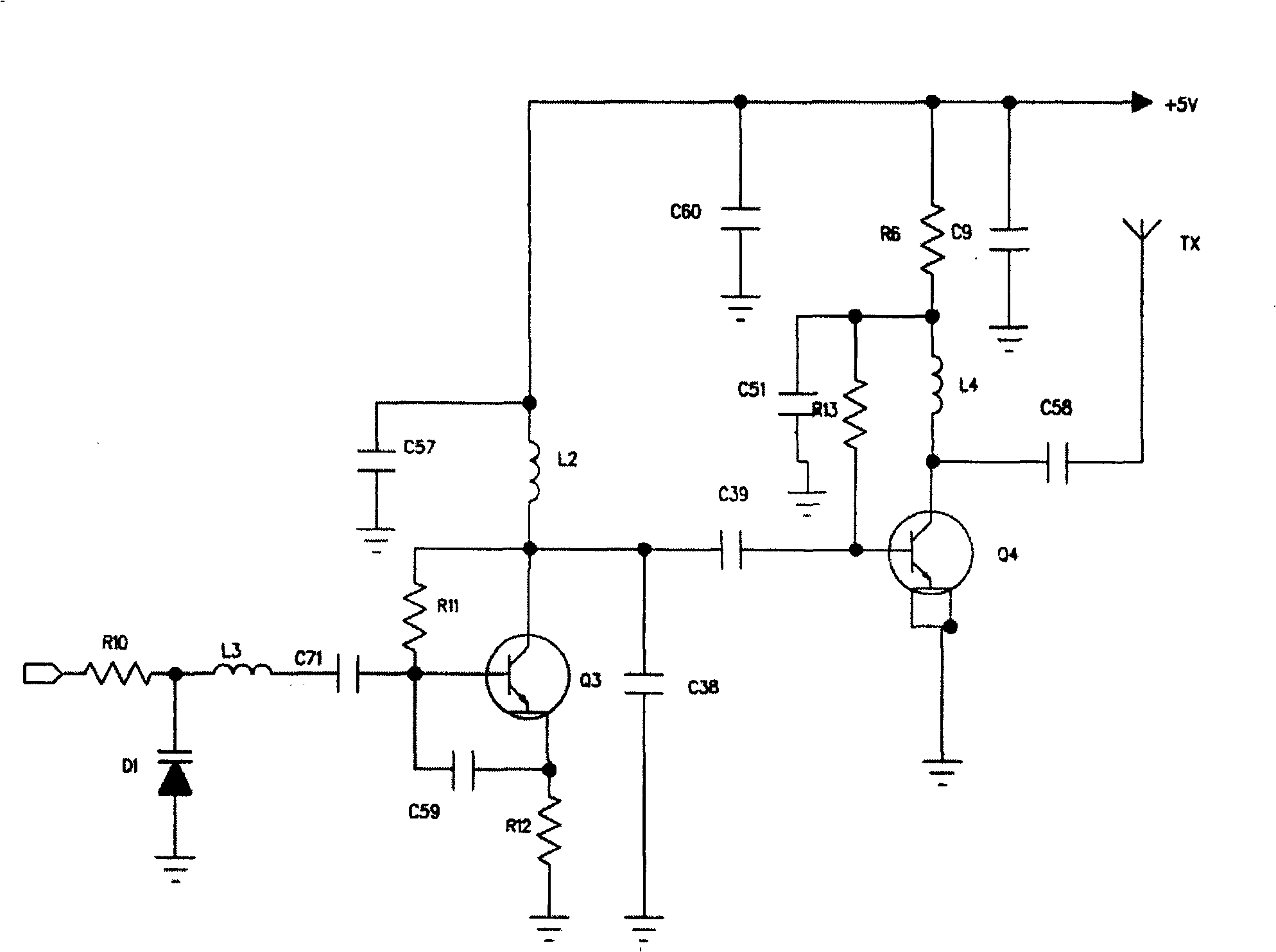
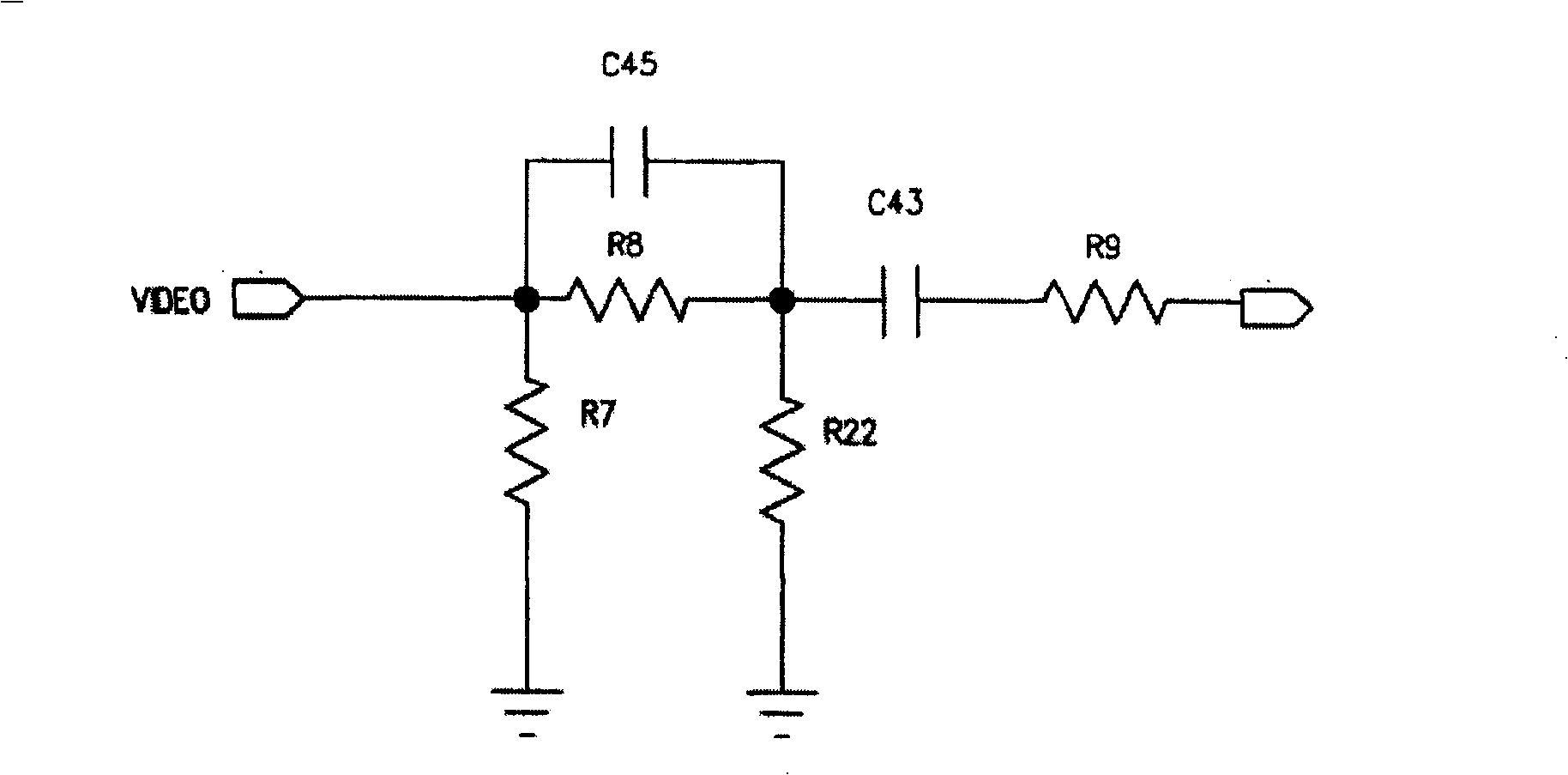
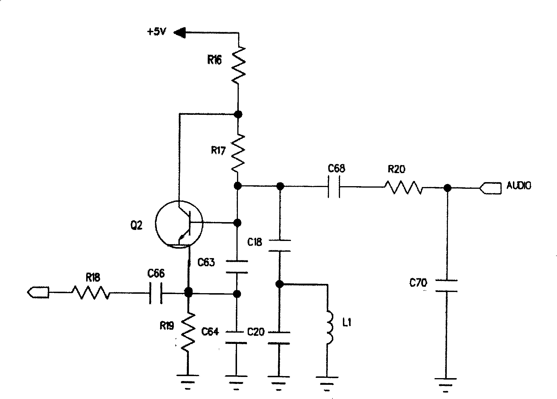
[0021] Below in conjunction with accompanying drawing and embodiment the present invention is further elaborated:

[0022] Such as Figure 1 to Figure 5 As shown, all are schematic diagrams of the circuit used in the present invention. The external light is converted into an electrical signal through the photosensitive device, and then further processed by the video input circuit, and the video signal of a specific frequency range is output to the input end of the voltage-controlled oscillation circuit; Similarly, the external sound is converted into an electrical signal through an acoustic-electric conversion device (such as a microphone), and after corresponding processing by the audio input circuit, an audio signal of a specific frequency range is also output to the input end of the voltage-controlled oscillation circuit; the video signal and The audio signal is oscillated and modulated by the voltage-controlled oscillating circuit to become an audio and video signal in a f...


PUM


Abstract

An audio-video wireless emitting device comprises an audio input circuit, a video input circuit and a voltage-controlled oscillation circuit. The audio input circuit and video input respectively inputs audio signals and video signals to the input end of the voltage-controlled oscillation circuit that modulates the signals and outputs corresponding emission signals and emits out the signals through an antenna. Advantages: increased emission frequency stability as adopting single-chip machine to control emission frequency, 100 m emission distance in open environment, clear picture and non-distortion of sound.

Description

[technical field] [0001] The invention relates to the field of security protection, in particular to an audio and video wireless transmitting device. [Background technique] [0002] In the field of security, monitoring and management is one of the commonly used methods. The personnel on duty can understand the security situation of the monitored places through the pictures displayed in the monitor and the output sound, especially in supermarkets, shopping malls, residential quarters and other places. Management is more general. To manage by means of monitoring, it is generally necessary to install cameras on each main channel to achieve monitoring of the channel. At present, there are two forms of connection between the camera and the display, one is wired and the other is wireless. The former is mainly suitable for smaller occasions, and there are still wiring problems. If it is used in larger occasions, installation will encounter many difficulties. With the increase of ...

Claims


Application Information

Patent Timeline
Patent Type & Authority Patents(China)
IPC IPC(8): H04N5/38H04N7/18
Inventor 邓明友
Owner 邓明友
Why Eureka
Try Eureka