
Cool/hot wind device

A technology of cold and warm air and inner pipes, which is applied in the direction of refrigerators, refrigeration and liquefaction, heating and refrigeration combination, etc., can solve the problems that it is difficult to achieve the expected effect, and achieve the effect of saving space, avoiding the inflow of cement, and reducing the height

Inactive Publication Date: 2009-02-04
赤冢心义 +2
View PDF6 Cites 0 Cited by
  • Summary
  • Abstract
  • Description
  • Claims
  • Application Information

AI Technical Summary

Problems solved by technology

[0004] However, the warm wind or cold wind blowing into the air circulation channel first needs to heat or cool the air in the air circulation channel, and the air in the air circulation channel heats or cools the ground, so that the indoor cooling and heating effect can be achieved. Possibly, for this reason, depending on how critical the volume of the air collision space formed in the air circulation channel is, it is necessary to adjust the amount of air blown out by the forward pipe or the amount of air absorbed by the return pipe, plus this adjustment It is very delicate. In addition, the ground is mostly concrete, but it is very difficult to achieve the desired effect with the construction of the concrete floor.

Method used


Image

  • Cool/hot wind device
  • Cool/hot wind device
  • Cool/hot wind device

Examples


Embodiment Construction

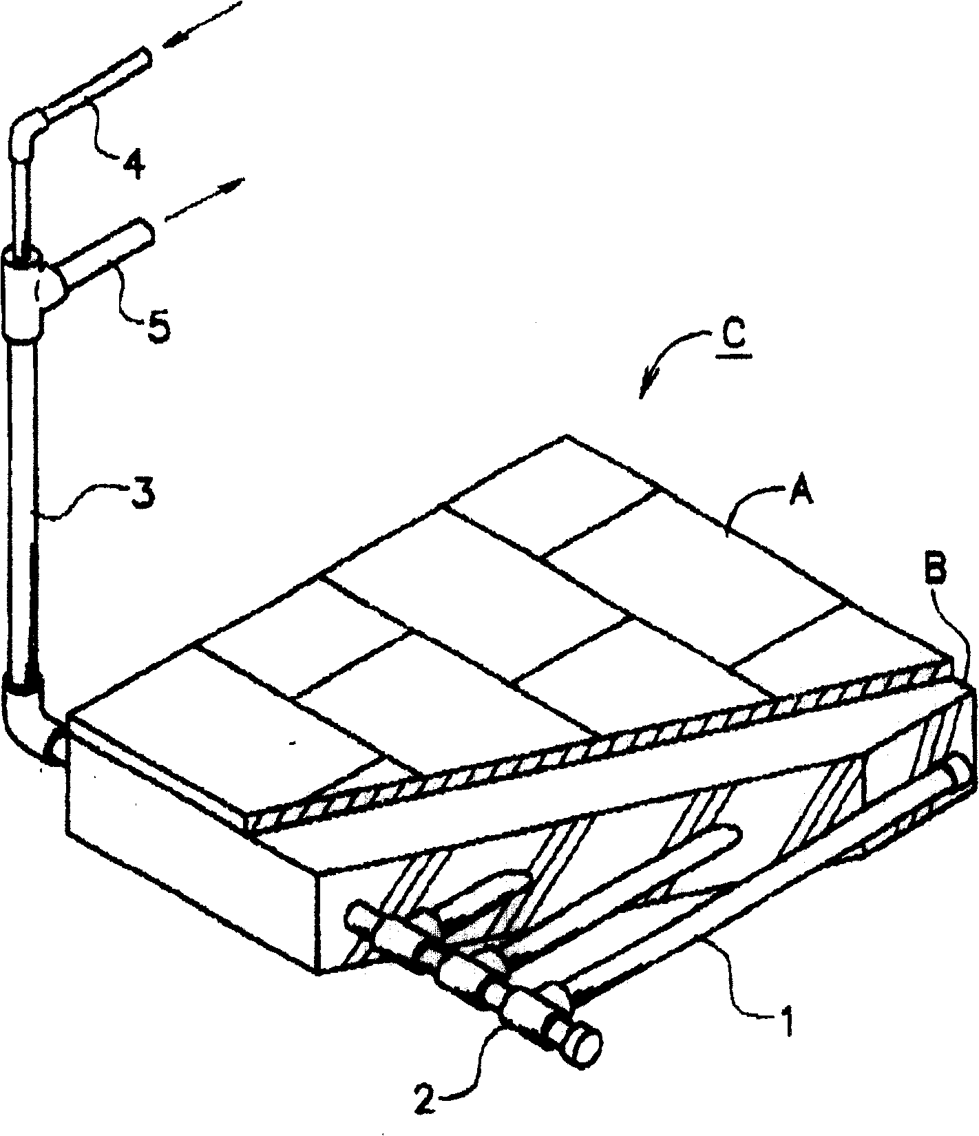
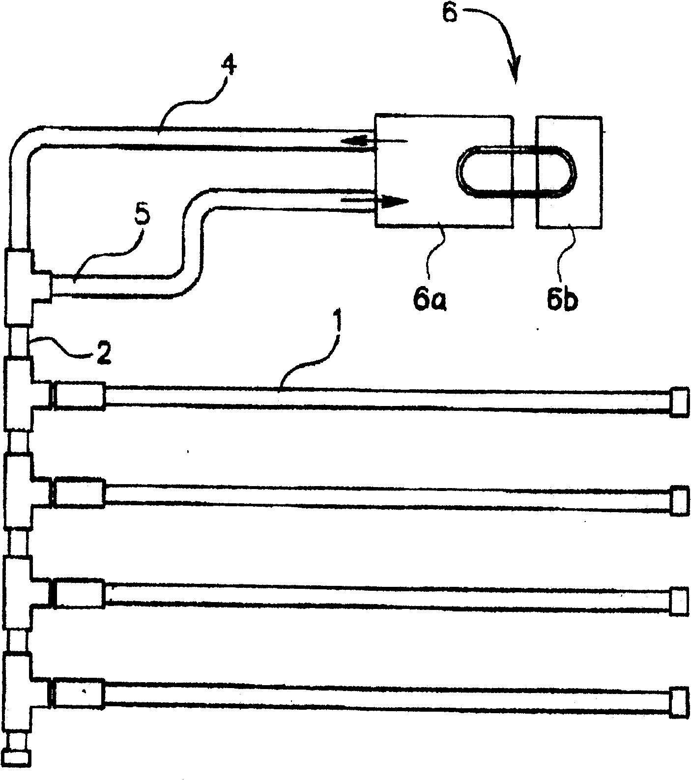
[0033] Hereinafter, the implementation conditions of the present invention will be described with reference to the accompanying drawings. The conditions of this implementation are as figure 1 As shown, below the floor A is a ground structure C poured with concrete B, and a double-layer circulating pipeline 1 is laid in the concrete B. The circulation pipelines 1 are laid under the floor A and laid in parallel at appropriate intervals. The intervals between the circulation pipelines 1 should be between 25cm and 30cm. The circulation pipeline 1 is connected with the double-layer pipe head 2, and the double-layer pipe head 2 is connected with the vertical pipe 3 and the heat exchanger. The standpipe 3 is separated into an inner pipe 4 and an outer pipe 5 on the way, and the inner pipe 4 is connected to the air supply port of the heat exchanger to form the outgoing pipe 4; the outer pipe 5 is connected to the air suction port of the heat exchanger to form the return pipe 5.

[0...


PUM


Abstract

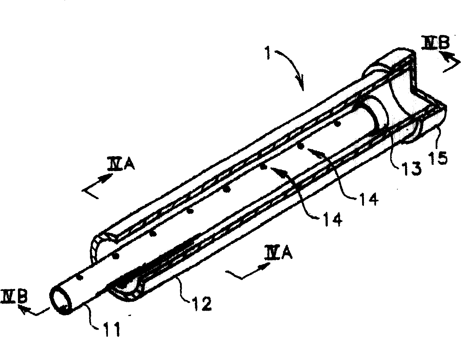
The invention discloses a cool-and-warm fan device for heating or cooling of cold air or hot air circulation toward ground surface, which is characterized by the following: the two layer structure of inner tube and outer tube is buried underground to form circulation pipe at certain distance, which is composed of two layer pipe head of inside branch pipe in connection with inner pipe and outside branch pipe in connection with outer pipe and spraying or sucking warm air or cool air heat converter; burying the circulation pipe underground at certain distance in connection with spraying side and two layer pipe head inside branch pipe; the go-course is composed of inside pipe; connecting the suck end of heat converter with outside branch pipe of two layer pipe head; the come-course is composed of outside pipe; the inside pipe is composed of sealed end head through certain distance piercing hole on the body; the outside pipe is composed of sealed metal pipe.

Description

technical field [0001] The present invention relates to a cooling and heating device, in particular to a device for heating or cooling by circulating cold or warm air underground. Background technique [0002] To blow warm or cold air underground and circulate it as a means of heating or cooling is to lay an air circulation channel with a certain air collision space, and while laying an air circulation channel underground, make the air circulation channel Warm or cold air is blown out of the space to form an outgoing pipe, which forms a system with the return pipe that absorbs the internal air. [0003] The above-mentioned conventional technology is based on the structure of heating or cooling the ground by the warm or cold air blown from the outgoing pipe. Therefore, the warm or cold air blown from the outgoing pipe must be sufficiently heated in the air circulation passage. Therefore, the air flow in the air collision space in the air circulation channel is very important...

Claims


Application Information

Patent Timeline
Patent Type & Authority Patents(China)
IPC IPC(8): F24D5/10F25B29/00
Inventor 赤塚心義
Owner 赤冢心义
Learn More