Multifunctional mop washing and dewatering machine

A multi-functional, dehydrator technology, applied in cleaning machinery, carpet cleaning, floor cleaning, etc., can solve problems such as water purification and water waste, reduce labor intensity, avoid excessive flushing, and avoid moving.

Inactive Publication Date: 2009-02-11
孟少甫
View PDF8 Cites 2 Cited by
  • Summary
  • Abstract
  • Description
  • Claims
  • Application Information

AI Technical Summary

Problems solved by technology

Therefore, what people face is not only the helplessness of "water droplets flow with the mop" that the mop cannot be dehydrated, but also the waste of water resources that continues "washing repeatedly, and clean water flowing in vain"

Method used


Image

  • Multifunctional mop washing and dewatering machine
  • Multifunctional mop washing and dewatering machine
  • Multifunctional mop washing and dewatering machine

Examples


Embodiment 1

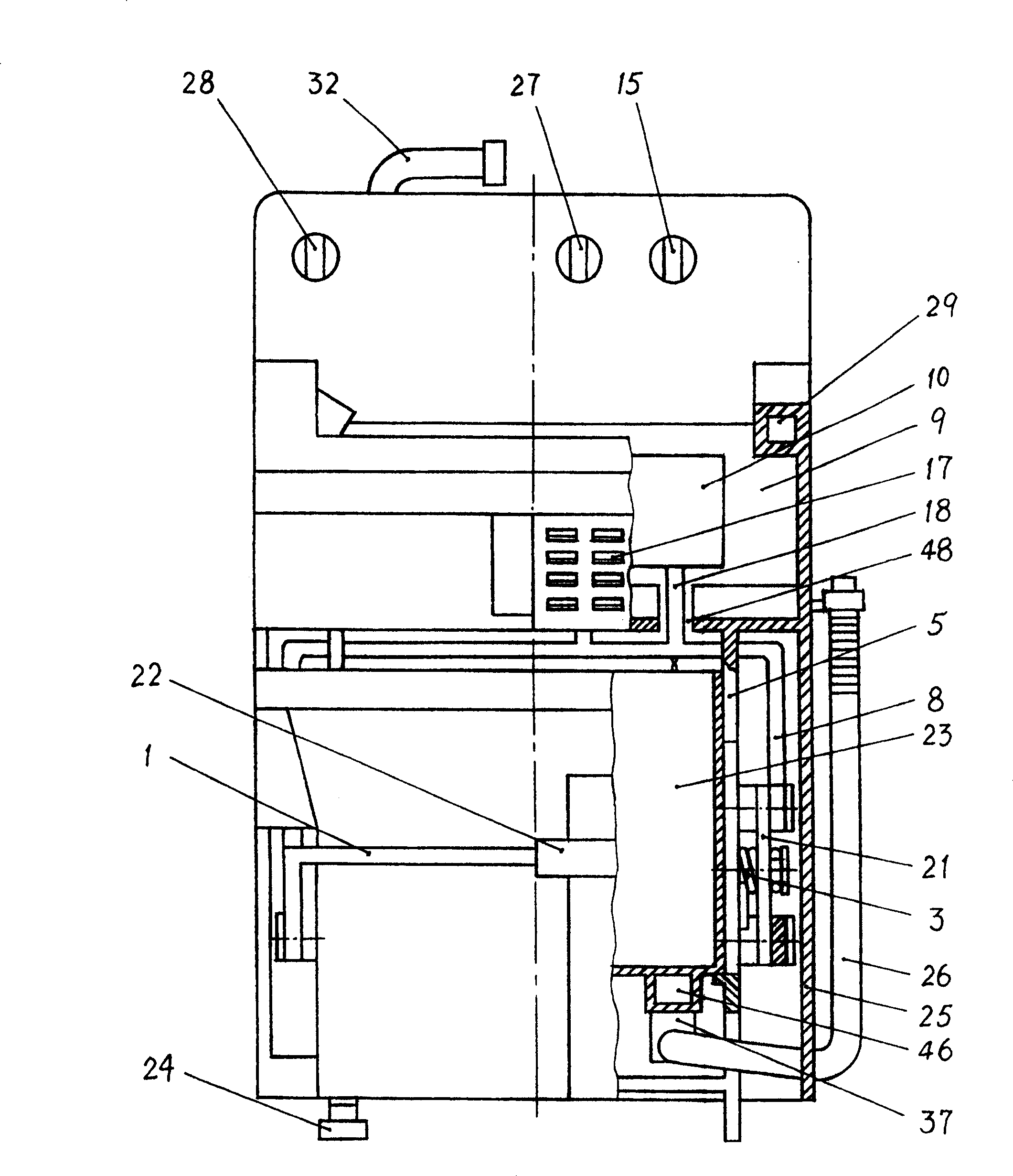
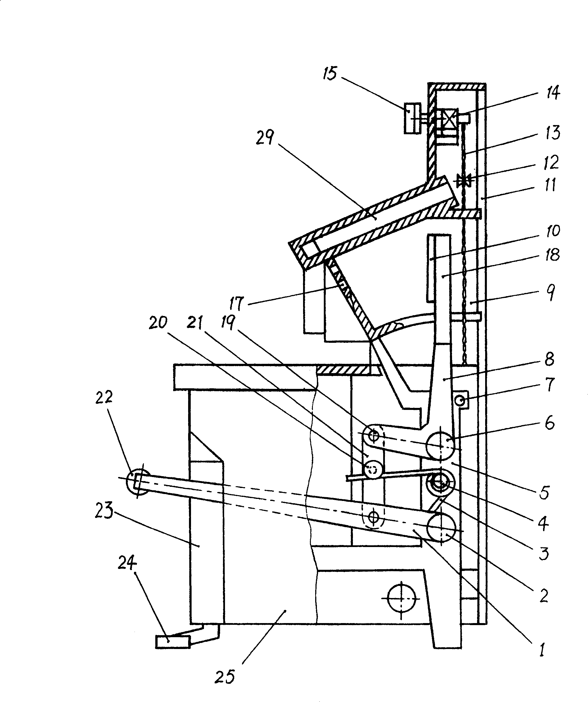
[0024] Such as figure 1 , figure 2 As shown, the frame 5 of the cleaning and dehydrating machine of the present invention is a vertical frame structure, and an upper pool 9 with an upper opening is installed on the top of the frame 5, and the upper mouth of the upper pool 9 is tilted forward to facilitate the cleaning operation of the mop in the pool . Such as Figure 5 As shown, a plurality of water outlet holes 47 are provided at the bottom of the upper pool 9, and the water outlet holes are all located above the lower pool 23, so that the outflowing cleaning waste water directly falls into the lower pool. Pedal driving mechanism is housed on frame 5, and the top of pedal driving mechanism stretches into upper pond 9, connects dynamic pressure plate 10. Figure 5 Among them, the dynamic pressure plate 10 connected with the pedal drive mechanism is arranged on one side in the upper pool 9, and the flushing of the mop is on the other side of the upper pool, so as to satisf...

Embodiment 2

[0037] Such as Figure 7 , Figure 8 As shown, the frame 5, the upper pool 9, the lower pool 23 and / or the water inlet pipeline, the control valve and other parts in the present embodiment are all the same as the corresponding parts in the embodiment 1, and the present embodiment is mainly for the pedal drive mechanism The structure has been simplified.

[0038] This pedal drive mechanism is to connect the inflection points of the two bent side arms of the door type pedal bar 1 through the rotating shaft 49 respectively on the two side vertical plates of the frame 5 positioned at both sides of the lower pool 23, and the two bent sides The upper end of the outrigger extends horizontally, passes the bar hole 48 on the side wall of the upper pool 9, and joins with the dynamic pressure plate 10 in the upper pool. Similarly, in order to make the pedal drive mechanism return automatically, a reset torsion spring 3 is connected to the side vertical plate of the frame 5, and one end...


PUM


Abstract

The multifunctional mop washing and dewatering machine for use in household has the structure comprising one frame, one upper tank with water outlet in the bottom, one lower tank with water draining port in the bottom, one foot operated driving mechanism with upper end extending into the upper tank and one movable pressing board connected to the top of the foot operated driving mechanism. The upper tank is used in washing and dewatering mop, and the lower tank is used for collecting waste water for reuse. The present invention has the functions of washing mop and dewatering mop, and is water saving.

Description

technical field [0001] The invention relates to a household washing device, in particular to a multifunctional mop cleaning and dehydrating machine. Background technique [0002] Over the years, in order to solve the dehydration problem of the traditional brush mop, many inventions emerge in an endless stream, and there are many new products on the market. Summarize roughly be divided into two classes: the first kind is the invention that is done on the mop bar, promptly adds some devices on the mop bar, to extrude the mop head, make it dehydrate. Compared with the traditional mop, this kind of invention and products cause certain inconvenience to use due to the existence of additional devices, so the application area is relatively narrow. Second class is the invention of utensil class, designs a kind of independent mechanical device exactly, to carry out dehydration to mop. This type of instrument-type mop dehydrator is more typical with a squeeze trolley, and is mainly u...

Claims


Application Information

Patent Timeline
Patent Type & Authority Patents(China)
IPC IPC(8): A47L13/59A47L13/10
Inventor 孟少甫
Owner 孟少甫
Why Eureka
Try Eureka