Non-aerated tire piece combined tire
A non-inflatable, combined technology, used in non-pneumatic tires, tire parts, transportation and packaging, etc., can solve the problems of vehicle subversion, traffic accidents, tire leakage, etc., to achieve less dislocation deformation, improve overall quality, Reliable effect of connection and assembly
- Summary
- Abstract
- Description
- Claims
- Application Information
AI Technical Summary
Problems solved by technology
Method used
Image
Examples
Embodiment 1
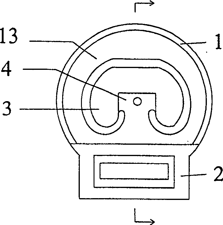
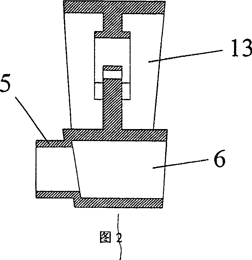
[0025] Embodiment 1: as figure 1 ,figure 2, Figure 11 , Figure 12 As shown, the non-pneumatic tire combined tire includes a steel ring 12, an inner tube and an outer tire 11. The outer tire 11 wraps the inner tube on the steel ring 12, and the inner tube is sequentially connected and assembled by the tires arranged along the steel ring 12 to form a closed The tire is circular, and the tire is made of highly elastic materials such as rubber, plastic or polyurethane, which are cast, molded or pressed, and then processed to remove burrs and defects. The different parts of the placenta are divided into the upper crown 1 and the lower placenta 2 according to their functions. There is a hollow cavity 3 in the middle of the crown 1, fan-shaped grooves 13 are set around the hollow cavity, and a limit platform 4 is set at the bottom of the hollow cavity 3. . When the tire is subjected to excessive pressure, the limit platform can prevent the excessive compression deformation of th...
Embodiment 2
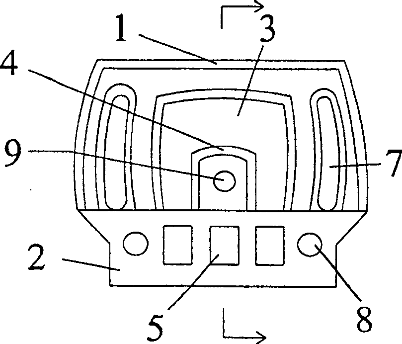
[0026] Embodiment 2: as image 3 , Figure 4 As shown, another implementation of the air-free tire inner tube is a structure suitable for use when the tire is under relatively high pressure. The basic structure is the same as that of embodiment 1, but the width of the tire is enlarged, and the tire seat 2 is provided with a through hole 8 to reduce weight, save material and increase the effect of elastic space. The connecting piece 5 and the connecting hole 6 are arranged symmetrically on both sides of the through hole 8 . Two deformation holes 7 are symmetrically opened on both sides of the original hollow cavity 3 on the tire crown 1. The purpose is also to reduce weight, save material, and increase elastic space. The spacer 4 at the bottom of the hollow cavity 3 should be correspondingly set larger, and an aperture 9 can also be arranged in the middle.
Embodiment 3
[0027] Embodiment 3: as Figure 5 , Image 6 As shown, yet another realization of the tire inner tube of the non-pneumatic-strip combined tire is a structure suitable for use when the pressure on the tire is small. As described below, the center of the crown 1 is a solid body made of high elastic material, and the rest of the basic structure is consistent with the first embodiment.
PUM
 Abstract
Description
Claims
Application Information
 - R&D
- Intellectual Property
- Life Sciences
- Materials
- Tech Scout
- Unparalleled Data Quality
- Higher Quality Content
- 60% Fewer Hallucinations
Browse by: Latest US Patents, China's latest patents, Technical Efficacy Thesaurus, Application Domain, Technology Topic, Popular Technical Reports.
© 2025 PatSnap. All rights reserved.Legal|Privacy policy|Modern Slavery Act Transparency Statement|Sitemap|About US| Contact US: help@patsnap.com


