Supercharge Your Innovation With Domain-Expert AI Agents!

An improved back suction valve for hot melting adhesives

A technology of valves and valve components, applied in the direction of valves, lift valves, valve devices, etc. to prevent dripping from nozzles, and can solve the problems of long stroke of suck back valve 10, slow valve speed, shortening the service life of seals, etc.

Inactive Publication Date: 2009-03-04
ILLINOIS TOOL WORKS INC
View PDF4 Cites 0 Cited by
  • Summary
  • Abstract
  • Description
  • Claims
  • Application Information

AI Technical Summary

Problems solved by technology

Therefore, while the dispensing of adhesive through the valve 10 is interrupted when the suck-back valve 10 is properly engaged by means of its associated drive mechanism or system (not shown), the suck-back valve 10 is of course able to reach its seat relative to the valve seat. Closed position, but the stroke of the suck-back valve 10 is quite long, so the speed of the valve is relatively slow
This will result in extensive wear of the seal components, and thus shorten the life of the seal. Large tolerances or clearance spaces together delay the initiation or completion of the valve suckback operation, so adhesive stringing can still occur

Method used


Image

  • An improved back suction valve for hot melting adhesives
  • An improved back suction valve for hot melting adhesives
  • An improved back suction valve for hot melting adhesives

Examples


Embodiment Construction

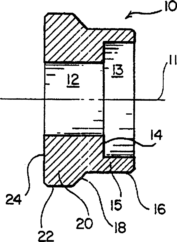
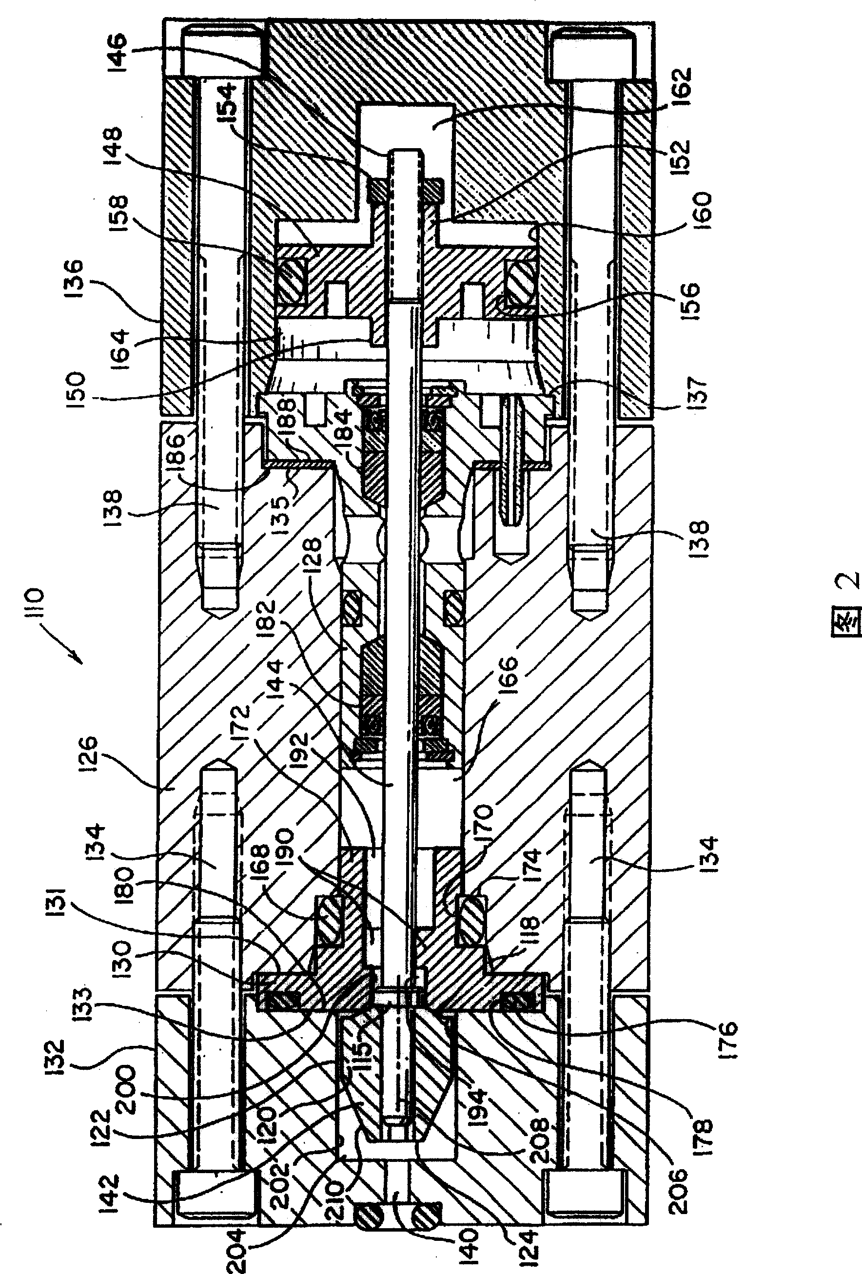
[0020] Referring now to the drawings, and in particular to FIG. 2 therein, there is illustrated and generally designated by reference numeral 110 a first embodiment of a novel and improved suckback valve assembly constructed in accordance with the principles and teachings of the present invention. It is worth noting that in the detailed description of the suckback valve of the present invention, those parts corresponding to those of the suckback valve of the prior art will be indicated with similar reference numerals, so that it may be easier to compare the valve of the present invention with the existing Valves of the present invention are compared, however, reference numerals representative of valve components of the present invention will be within the 100 series.

[0021] Accordingly, it will be seen that the suckback valve assembly 110 includes a body member 126 with a sealing cartridge assembly 128 disposed within a first end of the body member 126 and a valve seat member...


PUM


Abstract

A snuffback valve assembly (110) comprising a snuffback valve element (142) having a tapered frusto-conically disposed downstream end portion (210) for moving aerodynamically with respect to highly-viscous materials so as to effectively eliminate the phenomenon of bursting upon movement of the snuffback valve element from the closed to opened positions, and an upstream end portion which comprises an annular portion disposed perpendicular to the axis of the valve element, and a sharp-cornered region (206,122), for disrupting the flow parameters of the viscous material and for maintaining vacuum conditions within a valve chamber (204) so as to prevent stringing of the viscous material when the valve element (142) is moved from the opened to closed positions. <IMAGE>

Description

technical field [0001] This invention relates generally to dispensing systems for hot melt adhesives, and more particularly to a novel and improved suck-back valve for dispensing hot melt adhesives, thereby enabling rapid interruption of the supply of adhesives during dispensing The end of operation is achieved during closing of the valve so that undesired adhesive stringing does not occur. Background technique [0002] In connection with the dispensing of very viscous materials (e.g. hot melt adhesives) it is necessary that the dispensing system includes something well known in the art like a snuffback valve, by means of which it is easy to close the valve. The dispensed adhesive is shut off so that stringing of the adhesive does not occur. exist figure 1 A known prior art suck-back valve is disclosed in and generally designated by reference numeral 10 . The suck-back valve 10 is adapted to be fixedly mounted on a valve stem (not shown), which in turn is adapted to be fi...

Claims


Application Information

Patent Timeline
Patent Type & Authority Patents(China)
IPC IPC(8): F16K1/00F16K1/34F16K21/00B05B1/30B05C5/02B05C5/04F16K23/00F16K31/122
CPCF16K23/00B05C5/0225B05C5/02
Inventor 小爱德华·W·博利阿德马克·D·鲍尔
Owner ILLINOIS TOOL WORKS INC
Features
  • R&D
  • Intellectual Property
  • Life Sciences
  • Materials
  • Tech Scout
  • Unparalleled Data Quality
  • Higher Quality Content
  • 60% Fewer Hallucinations
Learn More