
Light shading and reflecting device for illuminator

A reflective device and illuminator technology, applied to illuminated signs, display devices, instruments, etc., can solve the problems of uneconomical, large volume, increased power consumption, etc., to achieve enhanced brightness, uniform illumination, and reduced number of lamp tubes Effect

Inactive Publication Date: 2009-03-04
BEIJING TONYEET LAN & PAM IND TRADE
View PDF6 Cites 1 Cited by
  • Summary
  • Abstract
  • Description
  • Claims
  • Application Information

AI Technical Summary

Problems solved by technology

However, this lampshade structure cannot completely eliminate the rib pattern phenomenon, and because the distance between the lampshade and the soft plate is enlarged, the thickness of the light box is large, the volume is large, and raw materials and electric energy are wasted, which is neither economical nor beautiful.
[0004] Moreover, the design trend of the existing light boxes is to manufacture thin light boxes, so that the light emitted by the light tubes cannot be irradiated to a place with a relatively long distance, so more light tubes need to be installed, which eventually leads to an increase in power consumption

Method used


Image

  • Light shading and reflecting device for illuminator
  • Light shading and reflecting device for illuminator
  • Light shading and reflecting device for illuminator

Examples


Embodiment Construction

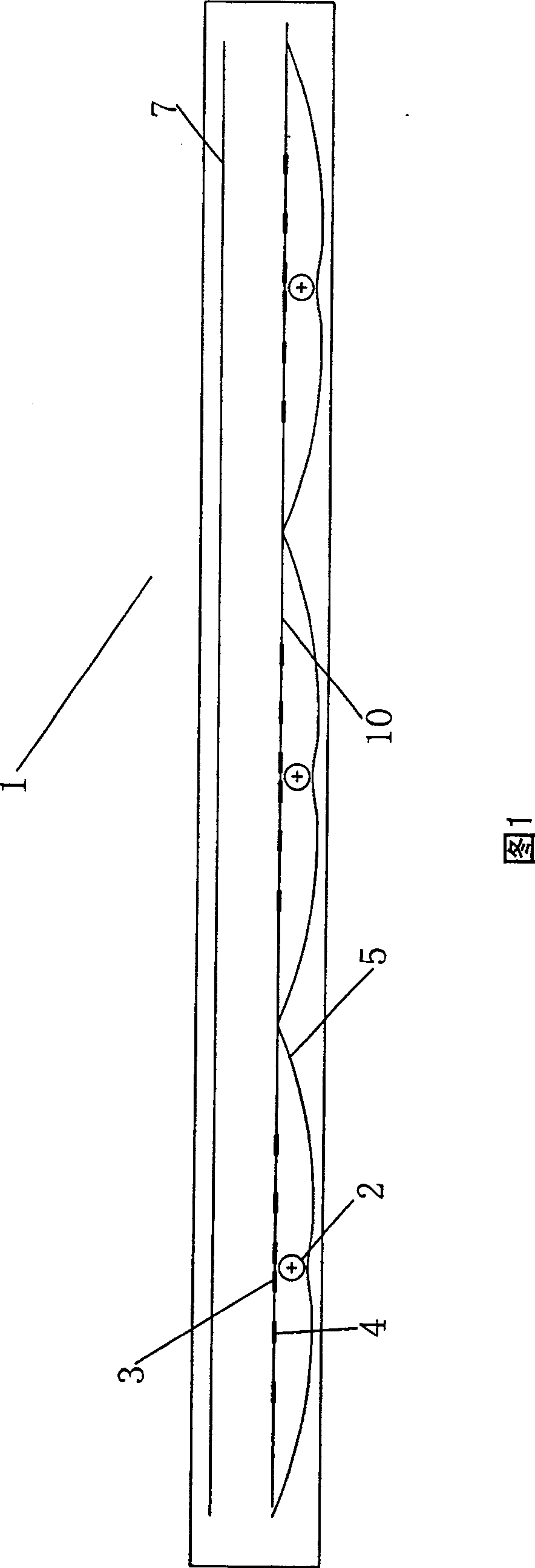
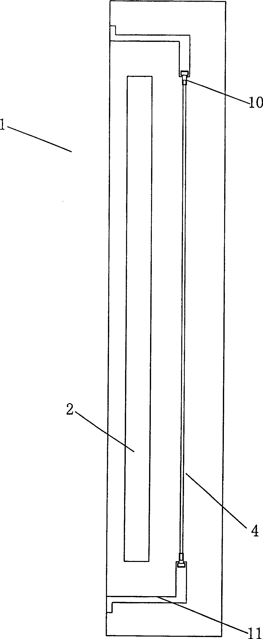
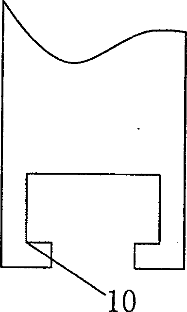
[0021] As shown in Figures 1-4, the light-shielding and light-reflecting device for guiding light source distribution provided by the present invention is shown. In the accompanying drawings, the arrangement of light shields and reflectors is shown by taking the distribution of light sources in the guide light box as an example. However, it will be appreciated that the invention is equally applicable to directing the light distribution of general luminaires.

[0022] As shown in Figure 1, a plurality of parallel light tubes 2 are arranged in the width direction of the light box 1, a transparent or translucent picture support plate 7 is arranged in the display direction of the light box, and a reflector 5 is arranged behind the light tubes 2, and the light tubes are oriented to display The front of the lamp is provided with reflectors 3 in front of the direction, and on the plane of the front end of the lamp tube, a number of reflectors 4 on both sides of the lamp tube are prov...


PUM


Abstract

The invention provides a colored glaze of an illuminator which comprises a lump pipe and a curl reflecting plate behind the lump pipe. It is characterized in that: the end part of the curl reflecting plate arranges lump pipe two sides reflecting sheet; it reflects the light from lump pipe and reflected by the curl reflecting plate to the remote place so that the light can evenly illuminate to the picture support plate.

Description

technical field [0001] The invention relates to a device for shading and reflecting light emitted by a lamp tube in an illuminator, in particular to a light-shielding and reflecting device for guiding the light from a lamp tube in a light box. Background technique [0002] A general interior lighting light box includes a box body, the picture is arranged in front of the box body, and several parallel light tubes are arranged in the box body. There is a certain gap between two adjacent light tubes, which will cause light vacancies. After turning on the light, there will be discontinuous and uneven light on the light box picture, that is, the common rib pattern phenomenon, which seriously affects the effect of the light box and the picture. [0003] In order to reduce the rib pattern phenomenon, it is generally necessary to install a soft plate in front of the light box, and increase the distance between the lampshade and the soft light plate to reduce the illuminance, thereby...

Claims


Application Information

Patent Timeline
IPC IPC(8): G09F13/04
Inventor 王默文
Owner BEIJING TONYEET LAN & PAM IND TRADE
Learn More