Lighting device for sheath flow optical imaging

An optical imaging and lighting device technology, applied in optics, measuring devices, optical components, etc., can solve the problems of complex imaging control and high price, and achieve the effects of guaranteed image quality, simple operation, and uniform lighting

Pending Publication Date: 2020-06-12
URIT MEDICAL ELECTRONICS CO LTD
View PDF0 Cites 0 Cited by
  • Summary
  • Abstract
  • Description
  • Claims
  • Application Information

AI Technical Summary

Problems solved by technology

[0003] At the same time, for high-speed sheath flow occasions, such as the current mainstream imaging flow cytometer with image acquisition function, such as the imaging flow cytometer developed by Amnis, a subsidiary of Merck

Method used


Image

  • Lighting device for sheath flow optical imaging
  • Lighting device for sheath flow optical imaging
  • Lighting device for sheath flow optical imaging

Examples


Embodiment Construction

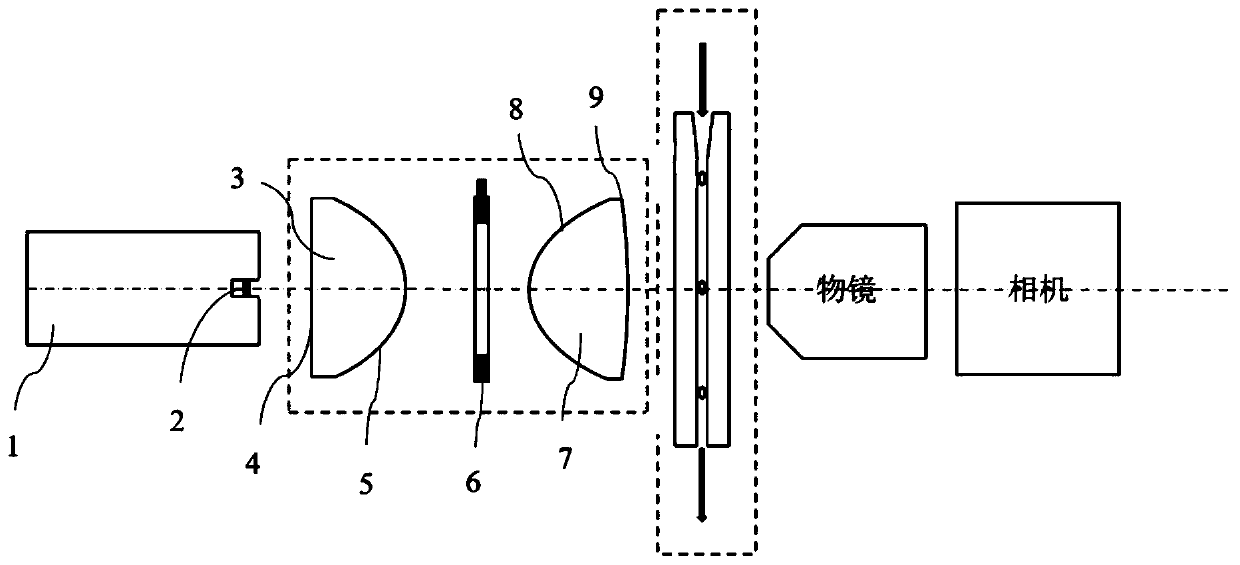
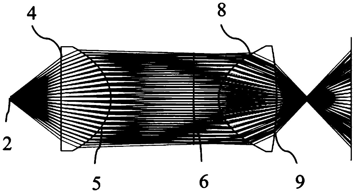
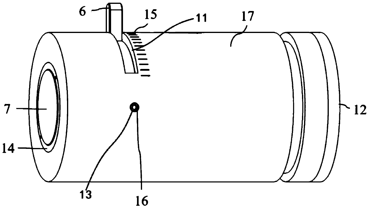
[0025] Embodiments of the present invention are described in detail below, examples of which are shown in the drawings, wherein the same or similar reference numerals designate the same or similar elements or elements having the same or similar functions throughout. The embodiments described below by referring to the figures are exemplary and are intended to explain the present invention and should not be construed as limiting the present invention.

[0026] In describing the present invention, it should be understood that the terms "length", "width", "upper", "lower", "front", "rear", "left", "right", "vertical", The orientation or positional relationship indicated by "horizontal", "top", "bottom", "inner", "outer", etc. are based on the orientation or positional relationship shown in the drawings, and are only for the convenience of describing the present invention and simplifying the description, rather than Nothing indicating or implying that a referenced device or element...


PUM

PropertyMeasurementUnit
Focal lengthaaaaaaaaaa

Abstract

The invention discloses a lighting device for sheath flow optical imaging. A stroboscopic xenon lamp is selected as the light source. The light collecting lens is a single aspheric lens; the first surface part is a 600-mesh scattering surface; the second face part is an even-order aspheric surface; the numerical aperture is greater than or equal to 0.6; the light receiving angle is greater than 90degrees, the third surface part is an even-order aspheric surface; the fourth face part is a standard spherical surface, the numerical aperture is larger than or equal to 0.75, the focal length is smaller than or equal to 16 mm, and the light convergence angle is 45 degrees, so that uniform illumination of a high-speed flowing sample in the sheath flow device is achieved, imaging smear of movingparticles is reduced, the image quality is guaranteed, and the sheath flow device has the advantages of being high in adjustability, easy to operate and low in cost.

Description

technical field [0001] The invention relates to the technical field of particle shape analysis for in vitro diagnosis, in particular to an illuminating device for optical imaging of sheath flow. Background technique [0002] At present, traditional electron microscopes use LED light sources and Kohler condensers to realize backlighting. This continuous lighting method has many advantages for imaging static samples, with stable and uniform brightness and high imaging sharpness. However, when using a traditional electron microscope to image the flowing particles in the sheath flow device, the obtained image will have very serious motion smear, the image is blurred and unclear, and it is impossible to analyze the shape of the target particle. The new fluorescent electron microscope and metallographic microscope have improved and upgraded the imaging system. By upgrading the exposure performance of the CCD camera, clearer imaging of moving particles can be achieved. However, the...

Claims


Application Information

Patent Timeline
IPC IPC(8): G01N15/14G02B21/06G02B21/08G02B21/00
CPCG01N15/1434G02B21/0004G02B21/06G02B21/08
Inventor 杨浩吴祝清朱福音陆庆彬郭建宝
Owner URIT MEDICAL ELECTRONICS CO LTD
Why Eureka
Try Eureka