Hot pipe

A heat pipe and shaft technology, applied in the field of heat transfer, can solve problems such as limiting the heat transfer efficiency of the heat pipe, and achieve the effect of improving the heat transfer efficiency and the heat transfer rate.

Inactive Publication Date: 2009-03-11
HONG FU JIN PRECISION IND (SHENZHEN) CO LTD +1
View PDF6 Cites 0 Cited by
  • Summary
  • Abstract
  • Description
  • Claims
  • Application Information

AI Technical Summary

Problems solved by technology

However, when it uses the flow of working fluid to transfer heat, the heat transfer efficiency of the heat pipe also depends on the flow velocity of the working fluid, and the existing heat pipe has not improved the flow velocity of the working fluid, which severely limits the heat transfer efficiency of the heat pipe. Improvement of transmission efficiency

Method used


Image

  • Hot pipe
  • Hot pipe
  • Hot pipe

Examples


Embodiment Construction

[0015] The present invention will be further described in detail below in conjunction with the drawings.

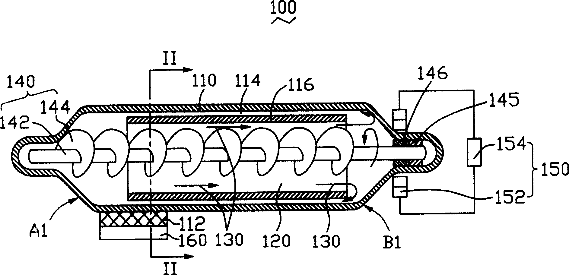
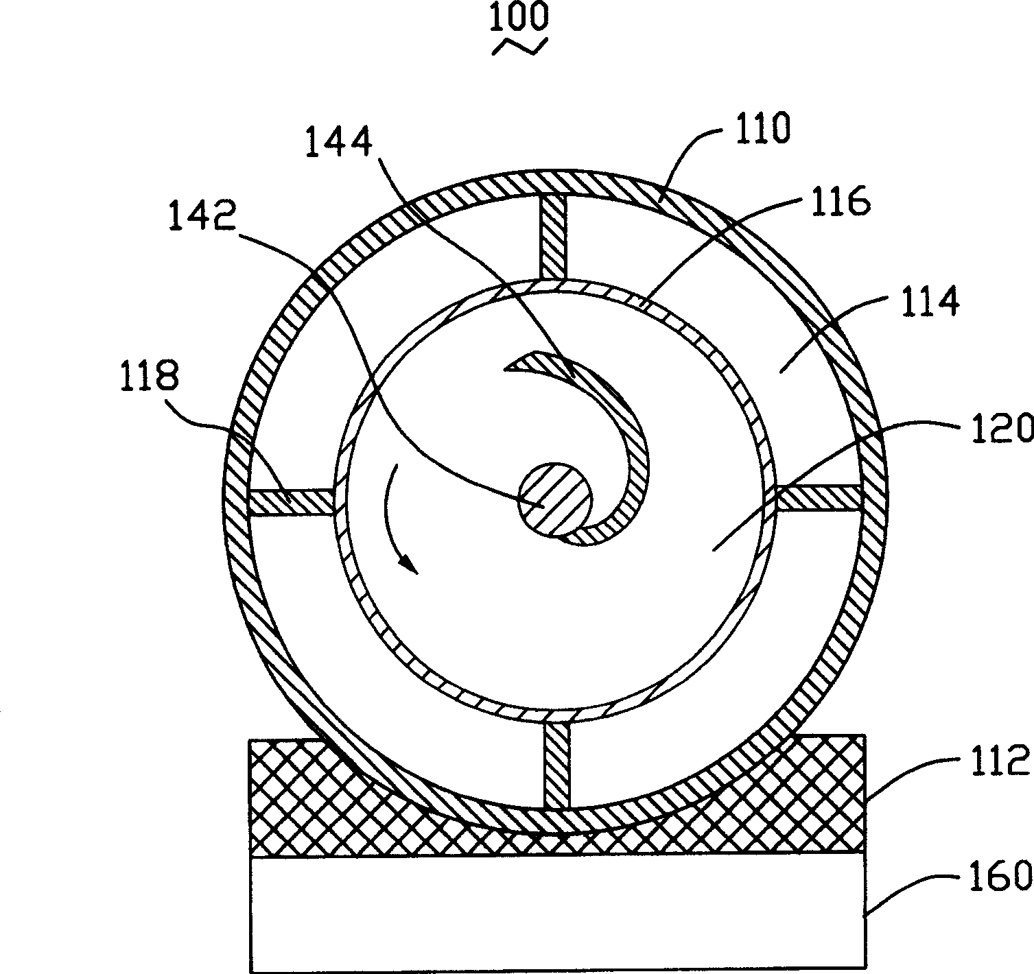
[0016] Please refer to figure 1 with figure 2 , Is the heat pipe provided by the first embodiment of the present invention. The heat pipe is a single-tube type heat pipe 100, and includes a hollow and hermetic shell 110 with a cavity 120 therein; the working fluid 130 sealed in the shell 110 A rotating device 140 arranged along the axial direction of the cavity 120 to accelerate the flow of the working fluid 130 in the heat pipe 100; and a driving device 150 arranged at one end of the housing 110.

[0017] Wherein, the hollow closed casing 110 usually includes an evaporating end A1 and a condensing end B1. The evaporating end A1 is in contact with a heat source 160. In order to increase the contact area therebetween, a heat dissipation patch 112 can be provided at the evaporation end A1. When the heat pipe 100 is used, the heat dissipation patch 112 is closely attached to t...


PUM


Abstract

The invention provides a heat pipe, comprising a hollow sealing shell, working fluid in said shell and a rotary device used to accelerate the flowing speed of working fluid in heat pipe. Said rotary device comprises rotary shaft set in shell in axial direction and agitating part formed on said rotary shaft. Cycle flow of working fluid in heat pipe is forced so that thermal migrating rate and heat transferring efficiency are improved by the rotation of rotary device in heat pipe.

Description

【Technical Field】 [0001] The present invention relates to the field of heat transfer technology, and particularly relates to a heat pipe that utilizes the flow of a working fluid to transfer heat. 【Background technique】 [0002] In recent years, the rapid development of electronic technology, the high frequency and high speed of electronic devices, and the density and miniaturization of integrated circuits have caused a sharp increase in the amount of heat generated by electronic devices per unit area. In order to dissipate the high heat generated by electronic devices, there are currently three general heat dissipation methods, namely, air-cooled heat sinks, liquid-cooled heat sinks and heat pipes. [0003] Air-cooled heat sink is currently the most widely used and most mature heat dissipation method, such as a fin type heat sink, which conducts the heat generated by the heat source to the heat sink through a metal base, and then uses the larger heat dissipation area of ​​the he...

Claims


Application Information

Patent Timeline
Patent Type & Authority Patents(China)
IPC IPC(8): F28D15/02
Inventor 张仁淙
Owner HONG FU JIN PRECISION IND (SHENZHEN) CO LTD
Why Eureka
Try Eureka