
Back light module

A backlight module, light source technology, applied in optics, nonlinear optics, instruments, etc., can solve the problems of light uniformity and low brightness, and achieve the effects of reducing production costs, reducing volume, and narrowing the difference between light and dark

Inactive Publication Date: 2009-03-11
HONG FU JIN PRECISION IND (SHENZHEN) CO LTD +1
View PDF13 Cites 0 Cited by
  • Summary
  • Abstract
  • Description
  • Claims
  • Application Information

AI Technical Summary

Problems solved by technology

[0006] In order to overcome the defects of low light uniformity and brightness of the prior art backlight module, the present invention provides a backlight module with high light uniformity and high brightness

Method used


Image

  • Back light module
  • Back light module
  • Back light module

Examples


Embodiment Construction

[0015] see Figure 4 , is a schematic perspective view of the first embodiment of the backlight module of the present invention. The backlight module 2 includes a light guide plate 20 and a light source 50 . The light guide plate 20 includes a light incident surface 21 and a light output surface 22 . Wherein, the material of the light guide plate 20 is a polymer resin material, such as polyacrylic resin, polycarbonate, polyethylene resin, polymethyl methacrylate, and can also be made of glass. The light emitting surface 22 has a plurality of prism structures 221 . The light source 50 is a point light source, which is arranged at the center directly in front of the light incident surface 21 . The prism structure 221 is arranged perpendicular to the light source 50 .

[0016] see again Figure 5 , is a front view of the backlight module 2 of the present invention. Wherein, the distance between two adjacent prism structures 221 of the light guide plate 20 is L, the width of...


PUM

PropertyMeasurementUnit
angleaaaaaaaaaa
widthaaaaaaaaaa

Abstract

The present invention relates to a backlight module. It includes at least a light source and a light-conducting plate. Said light-conducting plate includes a light-incoming plane for receiving incident beam of light source and a light-outcoming plane for deriving said beam, said light-incoming plane and said light-outcoming plane are crossed, said light source is set correspondently to said light source, and said light-outcoming plane has several prism structures, the more close to light source, the larger the spacing distance of said prism structures, the ratio value of said distance and said prism width is less than or equal to 99.

Description

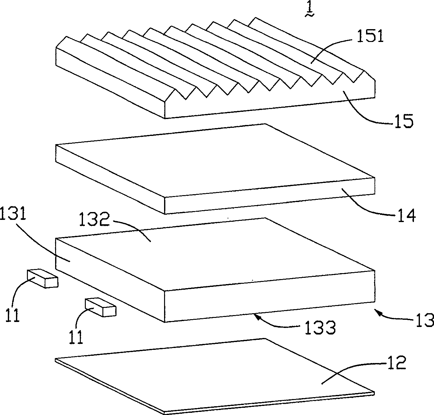
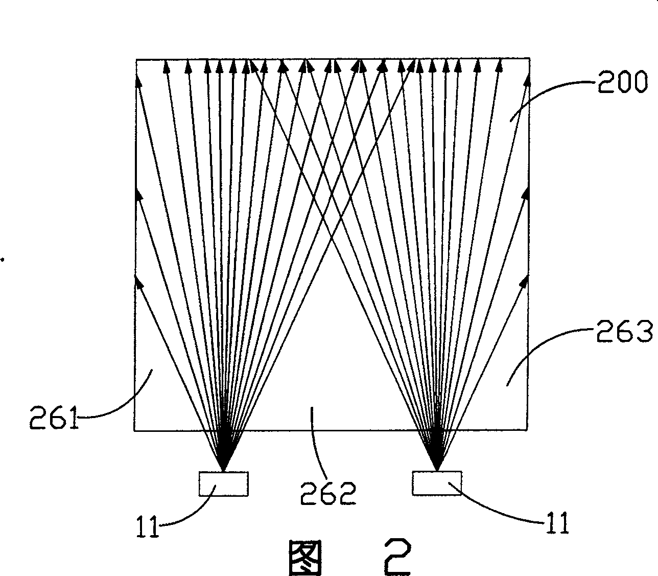
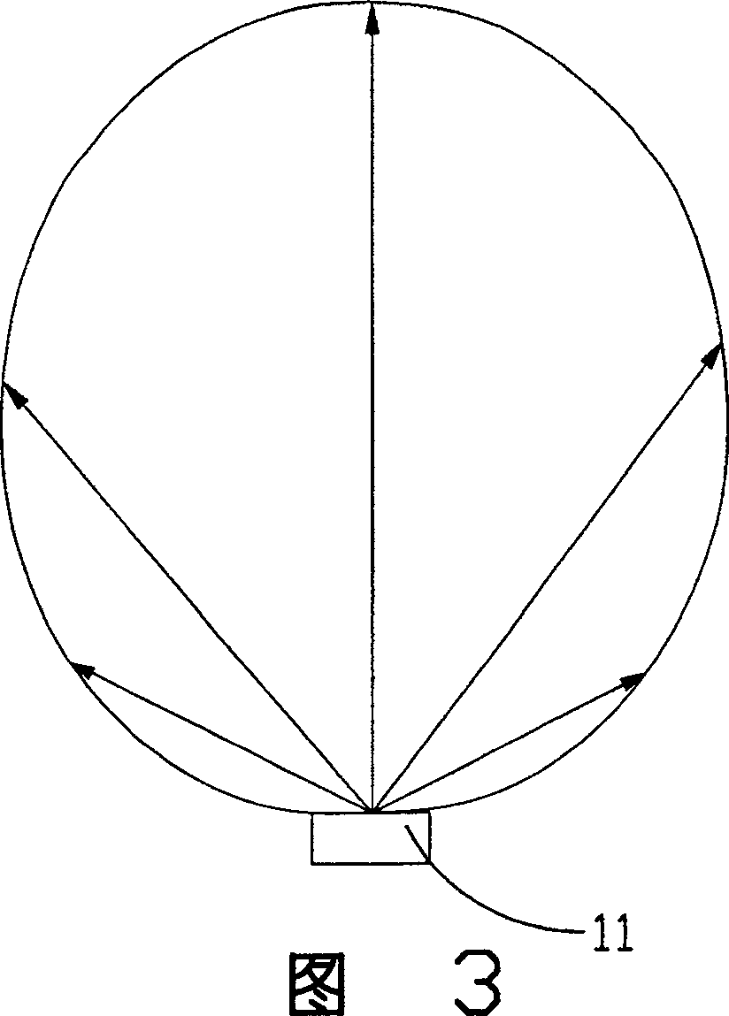
【Technical field】 [0001] The invention relates to a backlight module, in particular to a backlight module for a liquid crystal display. 【Background technique】 [0002] In recent years, with the colorization and enlargement of liquid crystal displays, their application fields are more extensive, such as notebook computers, various desktop computers, and LCD TVs. Because the liquid crystal display itself cannot emit light, it is necessary to use a light source system as the light source of the liquid crystal display, such as the backlight module (Backlight Module), wherein the light guide plate is an important component in the backlight module, used to guide the transmission direction of the light beam emitted from the light source , convert the line light source or point light source into a surface light source to emit. [0003] see figure 1 , is a prior art backlight module. The backlight module 1 includes two point light sources 11 , a reflector 12 , a light guide plate ...

Claims


Application Information

Patent Timeline
Patent Type & Authority Patents(China)
IPC IPC(8): G02F1/13357G02F1/1335
Inventor 余泰成吕昌岳陈杰良
Owner HONG FU JIN PRECISION IND (SHENZHEN) CO LTD
Learn More