Opening roller for rotor spinning machines

A rotor spinning machine and opening roller technology, applied in the field of steel wire saw racks, can solve the problems of increased pollution risk, unfavorable fiber damage, etc., and achieve the effect of improving the carrying function and preventing fiber damage

Inactive Publication Date: 2009-03-18
SAURER GERMANY GMBH & CO KG
View PDF5 Cites 1 Cited by
  • Summary
  • Abstract
  • Description
  • Claims
  • Application Information

AI Technical Summary

Problems solved by technology

[0005] As described in DE 41 24 714 A1 and DE 195 09 743 A1, the roughness of the tooth flanks of the tooth, especially high roughness, can lead to unfavorable fiber damage and to an increased risk of contamination through fiber wear

Method used


Image

  • Opening roller for rotor spinning machines
  • Opening roller for rotor spinning machines
  • Opening roller for rotor spinning machines

Examples


Embodiment Construction

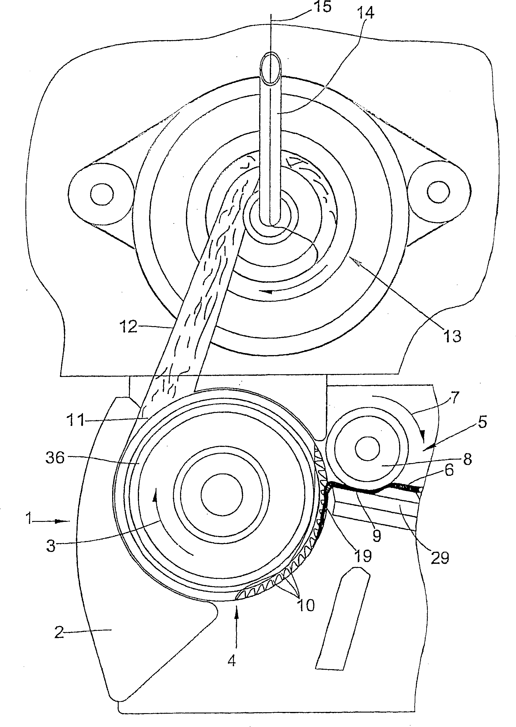
[0021] figure 1 The separating device 1 shown in includes an opening roller 4 which rotates in a housing 2 in the direction indicated by the arrow 3 . A feed device 5 is arranged upstream of the separating device 1 , by means of which the fiber web 6 is fed to the opening roller 4 . The feeding device 5 comprises a feed roller 8 which rotates very slowly relative to the opening roller 4 in the direction indicated by the arrow 7, which cooperates with a feed table 29 and is formed together with the feed table for the fiber Clamping position 9 for belt 6 . The supply roll 8 rotates continuously and conveys the fibers of the fiber strip 6 to the opening roll 4 . The opening roller 4 has a plurality of outwardly protruding teeth 10 on its circumference. The teeth can be produced, for example, by winding a wire saw tooth bar on the base body 36 of the opening roller 4 . If the fiber material of the fiber strip 6 reaches the range of action of the teeth 10 , a so-called fiber ma...


PUM


Abstract

An opening cylinder for rotor spinning machines comprises a plurality of teeth which are arranged in a line which extends in a continuous spiral-shaped manner on the periphery thereof. The advancing tooth flanks of the tooth form, respectively, an acute angle k of at least 1 DEG and at the most 2. 5 DEG with respect to the rotational direction of the opening cylinder during rotation, thus improving the function of the opening cylinder and the quality of the thread.

Description

technical field [0001] The invention relates to an opening roller for a rotor spinning machine according to the preamble of claim 1 and a wire sawtooth bar according to the preamble of claim 7 ( ). [0002] Such opening rollers are used to separate the fed fiber strip into individual fibers. The individual fibers are then conveyed from the opening rollers via fiber guide channels to the spinning rotors of the rotor spinning machine and spun into yarn. It is important for the function of the opening rollers rotating at high speeds that the entrainment of the individual fibers by the opening rollers is achieved in sufficient quantities, and that the centrifugal force and the negative pressure present at the end of the fiber guide channel , The detachment of individual fibers from the opening roller is not hindered. Background technique [0003] DE 41 24 714 A1 describes that drawing of the fibers takes place as long as the fibers of the fed fiber web are still held by feed...

Claims


Application Information

Patent Timeline
Patent Type & Authority Patents(China)
IPC IPC(8): D01H4/32
CPCD01H4/32
Inventor 海因茨-格奥尔格・瓦森霍芬克劳斯-迪特尔・兰多尔特海因茨-格奥尔格·瓦森霍芬克劳斯-迪特尔·兰多尔特
Owner SAURER GERMANY GMBH & CO KG
Why Eureka
Try Eureka