
Heat pipe

A heat pipe, copper tube technology, applied in the field of computer accessories, can solve the problems of encroachment, limited internal space, encroachment of internal hollow space, etc., and achieve the effects of improved performance, improved performance, and increased length

Inactive Publication Date: 2009-04-01
杨开艳
View PDF6 Cites 0 Cited by
  • Summary
  • Abstract
  • Description
  • Claims
  • Application Information

AI Technical Summary

Problems solved by technology

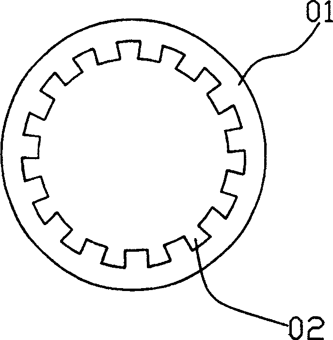
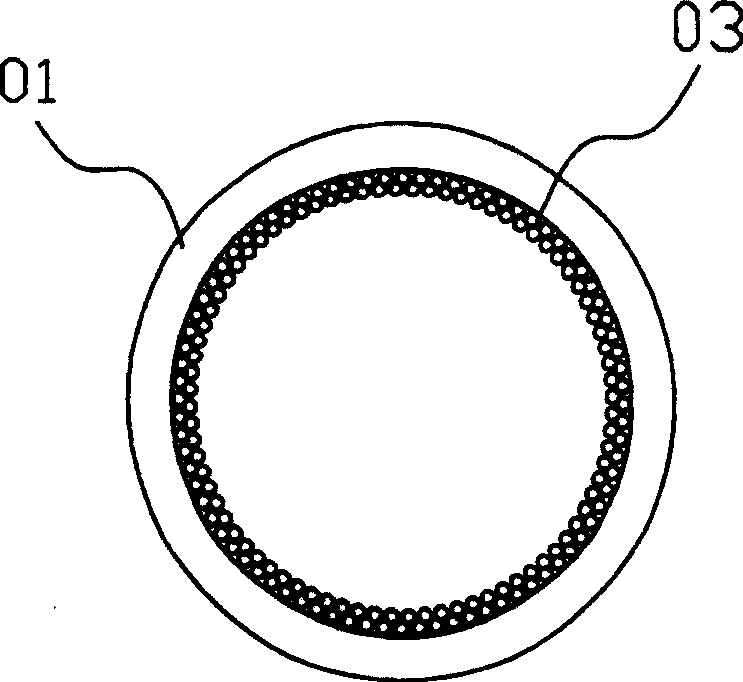
[0015] 1. Putting the braided mesh into the copper pipe is a direct insertion method. It cannot be guaranteed that the braided mesh at each position can be close to the inner wall of the copper pipe; the performance of each heat pipe is different, because if the braided mesh cannot be attached to the copper pipe The inner wall cannot play the role of auxiliary axial grooves to enhance the capillary phenomenon, so there must be another form to make the braided mesh close to the inner wall of the copper tube
[0016] 2. The wall thickness of the axial grooved heat pipe itself is thicker than that of the simple braided mesh pipe. If the braided mesh is added, the internal space is limited, not to mention the current requirements of electronic products to be thin and short; the diameter of the heat pipe is only 4 ~ 6mm (millimeters), if the braided mesh cannot cling to the inner wall of the copper pipe, but is deformed due to stress and invades the internal hollow space, it will not only fail to play the role of auxiliary axial grooves to improve capillary phenomenon, but will also hinder steam Run to the condensing end, not to mention that the heat pipe often has to be bent and flattened, which may deform the braided mesh, and cannot be close to the inner wall of the copper pipe, occupying the hollow space inside

Method used


Image

  • Heat pipe
  • Heat pipe
  • Heat pipe

Examples


Embodiment Construction

[0028] The following descriptions are only preferred embodiments embodying the principles of the present invention, and do not therefore limit the protection scope of the present invention.

[0029] As shown in accompanying drawing 3: the present invention has a copper pipe 10 with both ends closed, and a plurality of axial grooves 11 are engraved on the inner wall of the copper pipe 10. In addition, a metal braided mesh 20 is also provided in the copper pipe 10. The metal braided mesh 20 is combined with the end of the partition wall of the axial groove 11 through partial sintering. After the metal braided mesh 20 is partially sintered, on the one hand, the heat pipe will not deform the braided mesh due to bending and cause the problem of encroaching on its internal hollow space; There will be protrusions and bubbles on the surface of the metal woven mesh, which will roughen the surface, thereby increasing the adhesion of water and the metal surface to enhance capillarity, an...


PUM


Abstract

Present invention relates to computer fittings technology field, in particular referring to inner thermal pipe of computer radiator. Said thermal pipe has axial groove in inner wall and tubular metal mesh grid, said metal mesh grid partial sintering together with copper tube inner wall. Said invention enhances capillarity and improves performance when thermal pipe cooling end being lower than vaporization end.

Description

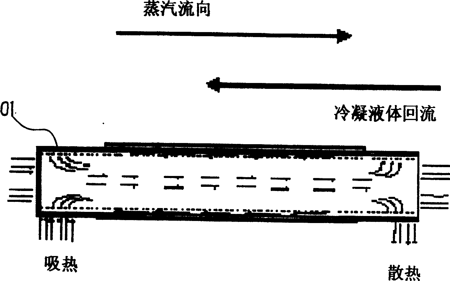
Technical field: [0001] The invention relates to the technical field of computer accessories, in particular to a heat pipe inside a computer radiator. Background technique: [0002] The calculation speed of the current electronic product chips is getting faster and faster, so the radiators used are gradually unable to meet the demand. In order to improve the heat dissipation rate of the metal sheet of the radiator, many radiators are currently equipped with heat pipes to improve heat conduction rate. [0003] As shown in accompanying drawing 1, the principle of the heat pipe is: a copper tube 01 sealed at both ends has a layer of medium (wick) that enables the liquid to transport the liquid by capillary action. When the liquid at the heating end is vaporized, along the From the central space to the cooling end, it is cooled to liquid again, and then returns to the heating end along the conveying medium along the inner edge, so that the purpose of rapid heat transfer can be ...

Claims


Application Information

Patent Timeline
Patent Type & Authority Patents(China)
IPC IPC(8): F28D15/04G06F1/20
CPCF28D15/046
Inventor 陈弘岳
Owner 杨开艳
Learn More