

Optical height adjusting device
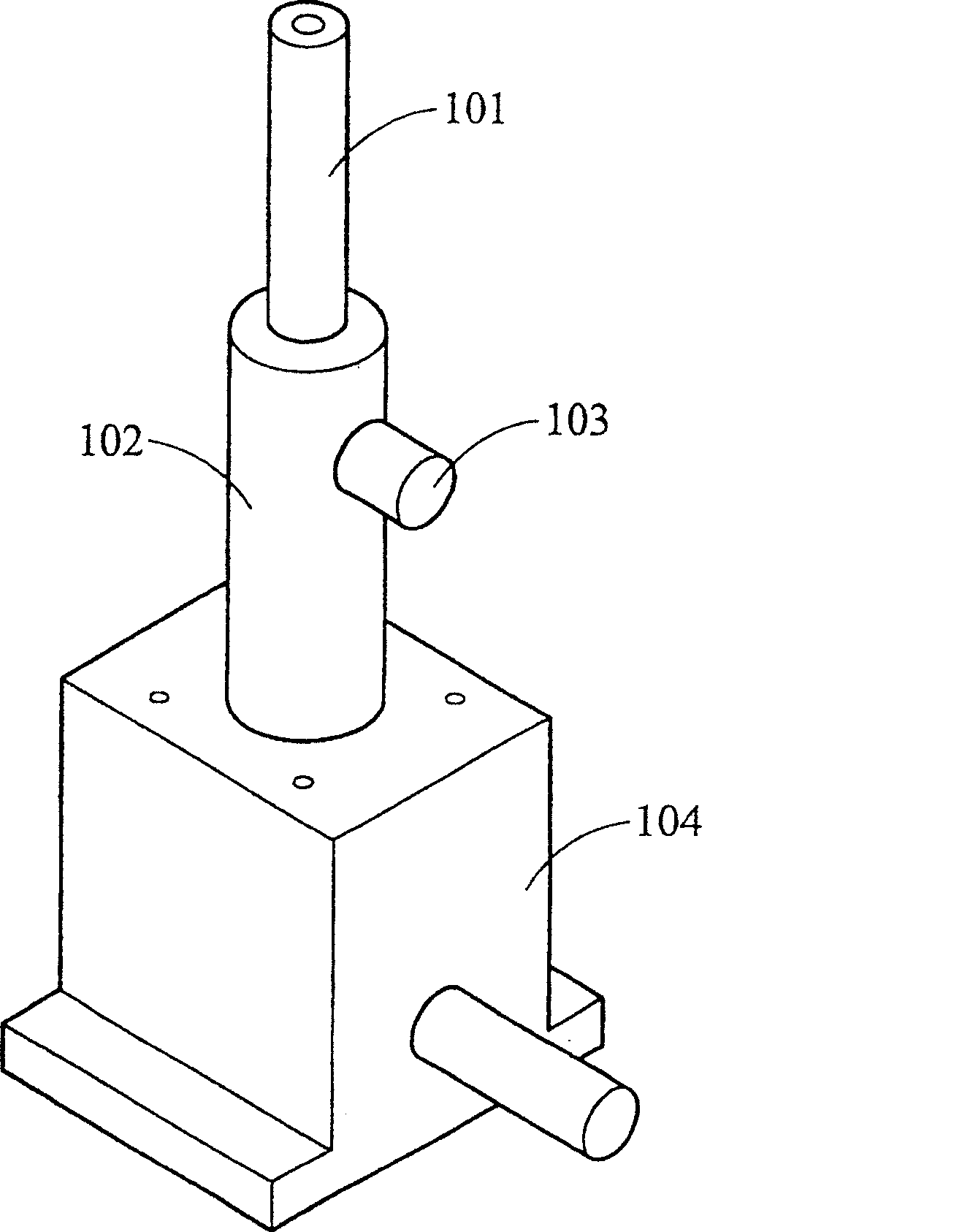
A technology of height adjustment and optics, which is applied to the parts of the instrument, instruments, etc., can solve the problems of complex structure, high price and time-consuming installation of the high-precision mobile platform 104
- Summary
- Abstract
- Description
- Claims
- Application Information
AI Technical Summary
Problems solved by technology
Method used
Image

Examples
Embodiment Construction
[0030] A preferred embodiment of the present invention will now be described with reference to the accompanying drawings.
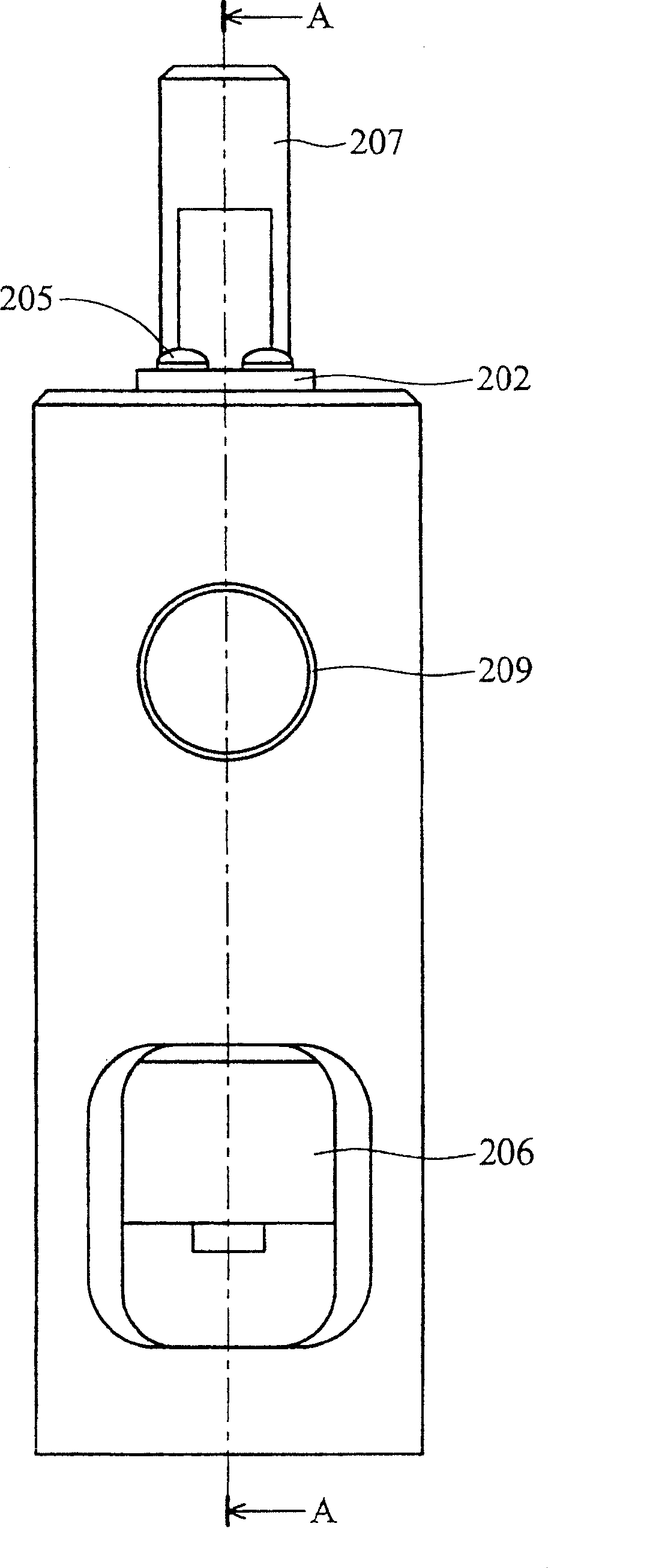
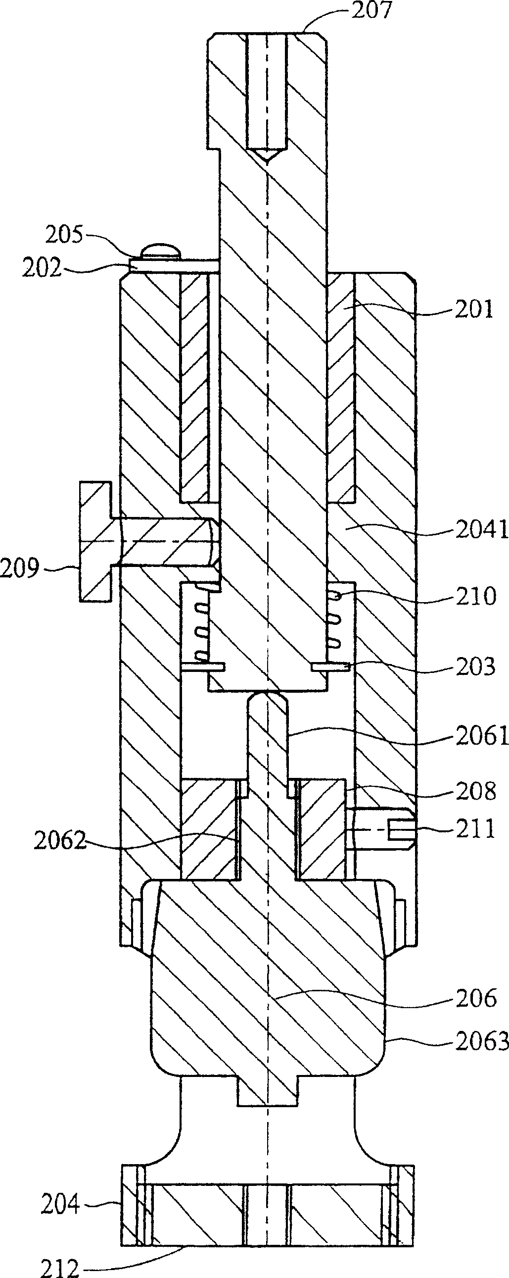
[0031] Such as figure 2 , 3 As shown, it is a preferred embodiment of the present invention, wherein a rod-shaped member 207 is installed in a base 204, and a buckle 203 is arranged at the bottom of the rod-shaped member 207 to fix a compression spring 210 to the rod-shaped member 207, the spring body of the compression spring 210 surrounds the rod member 207 and extends axially, and the other end of the compression spring 210 is in contact with the protrusion 2041 inside the base 204, so that the compression spring 210 is in contact with the buckle 203 and the protruding portion 2041 are compressed.
[0032] A screw mechanism 206 is located in the base 204, the screw mechanism 206 has a helical cylinder 2061, a neck 2062 and a rotating head 2063, rotating the rotating head 2063 of the screw mechanism 206 can make the helical cylinder 2061 move axially...
PUM
 Abstract
Description
Claims
Application Information