Cable clamp

A cable fixture and fixture technology, which is applied to electrical components, pipe supports, pipes/pipe joints/pipe fittings, etc., can solve the problems of easy breakage of cable fixtures, high manufacturing costs, and inconvenience in manufacturing, and achieves simple structure, convenient manufacturing, and manufacturing. low cost effect

Inactive Publication Date: 2009-12-09
DONG A BESTECH
View PDF0 Cites 15 Cited by
  • Summary
  • Abstract
  • Description
  • Claims
  • Application Information

AI Technical Summary

Problems solved by technology

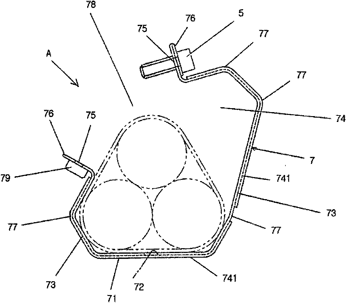
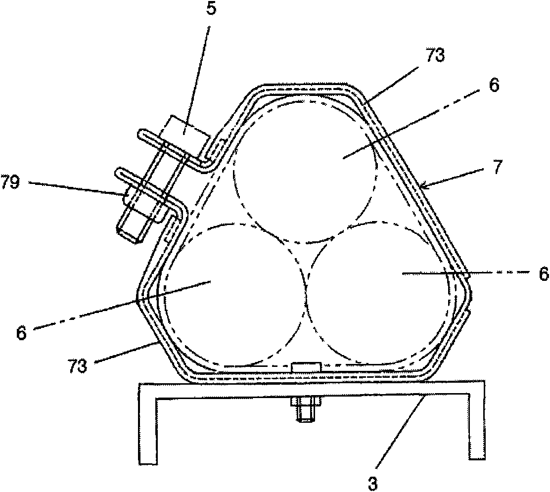
[0003] In order to solve the above problems, the applicant once proposed a cable clamp solution for fixing cables named "cable furniture", that is, the utility model registration No. 399792 application document of the Republic of Korea. This invention relates to a cable clamp that is easy to fix cables, such as figure 2 and image 3 As shown, it consists of a fixture body 7. A fixing groove is formed in the middle of the ground level part 71 of the fixture body 7, and side panels 73 that extend upward and zigzag are formed on both sides of the level part 71 to form cable receiving grooves 74. The ends of the side panels 73 pass through the fixing screw holes 75 to form joints 76 that can be connected to each other when fixed. The joints 76 at the above two ends form an entrance and

Method used


Image

  • Cable clamp
  • Cable clamp
  • Cable clamp

Examples


Example Embodiment

[0021] The cable clamp A in an implementation case of the present invention is such as Figure 4 , Figure 5 As shown, it is composed of a hinged fixing fixture body 2 and a fixture cover 3 that can be opened and closed according to the rotating operation of the hinge shaft 1. The above fixture body 2 and fixture cover 3 are able to increase the strength, and are protected by a double-thickness with repeated twists and turns. 21, 31 composition.

[0022] The clamp body 2 is formed with a clamping hole 22 in the middle, one end can be bent and extended upwards from the horizontal floor 24 with a hinge part 23 on the fixed hinge shaft 1 and the above horizontal floor 24, and one end is formed with an outwardly inclined joint 26; the clamp One end of the cover 3 has a hinge portion 33 that fixes the hinge shaft 1 and extends upward; in order to enable the cable to be received, it is connected to the upwardly convex curved portion 34 and the aforementioned curved portion 34, and at th...


PUM


Abstract

The invention relates to a cable clamp comprising a clamp body and a clamp cover with a fixed hinge and realizing opening and closing by the rotating operation of a hinge shaft. The clamp body and the clamp cover comprise dual thickness edges repeatedly folded to add strength; a clamping hole is formed in the center of the clamp body; one end of the clamp body can be arranged on a horizontal floor with a hinge part with the fixed hinge shaft and be upwards bent and extended together with the horizontal floor, and a combined part is formed at the other part of the clamp body; and one end of the clamp cover is provided with the hinge part with the fixed hinge shaft and can be extended upwards. A cable is connected to a curved bent part upwards protruding and bent for realizing receiving; and a curved combined part is formed, stuck to and fixed on the horizontal floor so that the curved bent part can be connected with the combined part of the clamp body; and a cable liner formed at a protruding bent part which is formed by dent bending and used for arranging a cable with a round end surface is attached to and fixed at the upper part. The invention is easy to fix large-diameter cables and cables of various diameters and has the advantages of simple structure, convenient manufacture, low manufacture cost, and the like.

Description

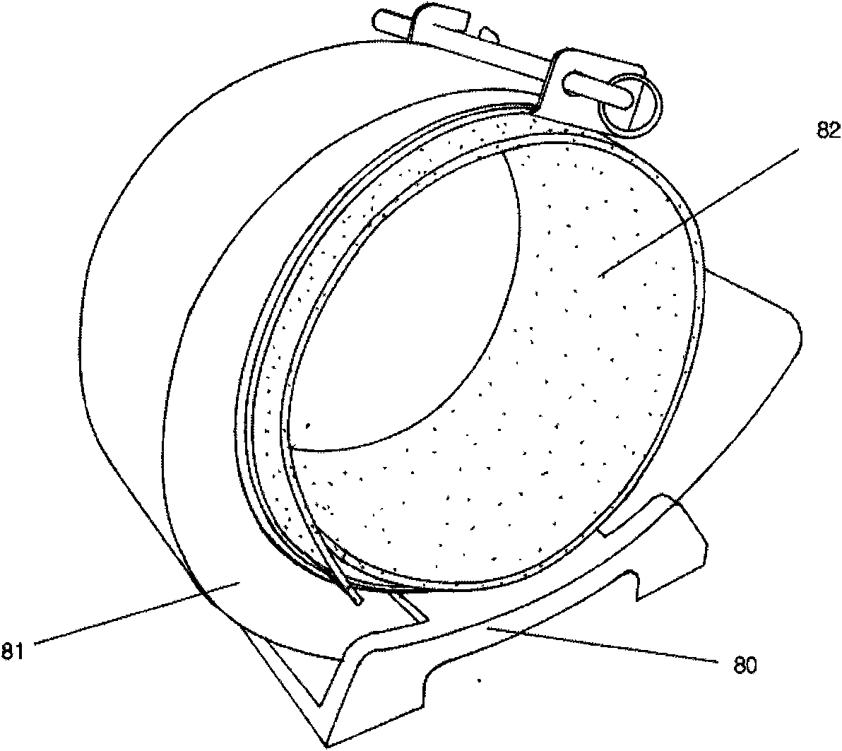
technical field [0001] The invention relates to a cable clamp. More specifically, it can easily fix cables such as large-diameter high-voltage lines or communication lines, improve construction capabilities, and shorten work time. It not only improves work efficiency, but also can fix cables with various diameters. Improved usage efficiency. [0002] Usually similar to cables such as large-diameter high-voltage wires or communication wires, due to the electromagnetic field or magnetic field generated when the power is applied, a huge elastic force will be generated between adjacent cables. To be fixed tightly, it should be fixed according to figure 1 As shown, secure with wide cable glands. In the past, in order to use gaskets for fixing, cable trays for fixing gaskets were installed in the fixed objects where cables were arranged, and wide cable gaskets were inserted between trays 80; at the same time, in order to protect cables, insert Then lay the cable on the cable pad, ...

Claims


Application Information

Patent Timeline
IPC IPC(8): F16L3/12H02G3/02H02G3/32
Inventor 裴准集
Owner DONG A BESTECH
Why Eureka
Try Eureka