
Intelligent antenna based on digital wave beam formation

A digital beam and smart antenna technology, applied in the field of mobile communication, can solve the problems of different structures and limited flexibility of smart antenna systems, and achieve the effects of optimizing network planning, increasing network capacity, and good compatibility

Inactive Publication Date: 2009-05-13
ZTE CORP
View PDF4 Cites 0 Cited by
  • Summary
  • Abstract
  • Description
  • Claims
  • Application Information

AI Technical Summary

Problems solved by technology

These changes lead to different structures of smart antenna system and non-smart antenna system, which limits the flexibility of use

Method used


Image

  • Intelligent antenna based on digital wave beam formation
  • Intelligent antenna based on digital wave beam formation
  • Intelligent antenna based on digital wave beam formation

Examples


Embodiment Construction

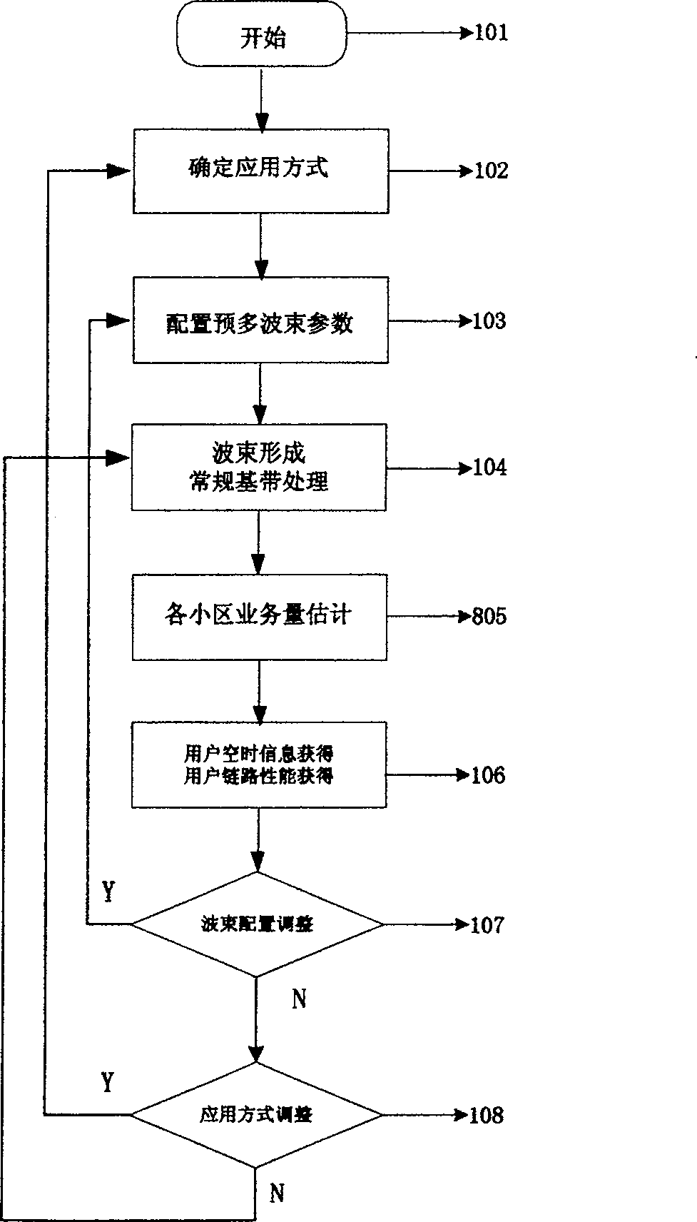
[0033] figure 1 is a flowchart of the method of the present invention.

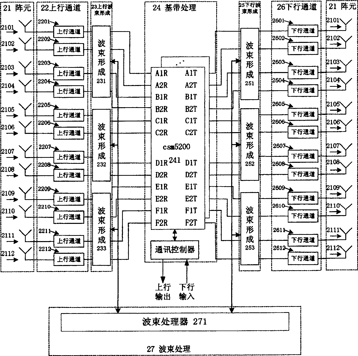
[0034] figure 2 It is an implementation block diagram of the present invention applied in WCDMA system. It includes: an array element (21), an uplink channel (22), an uplink beamforming (23), a baseband processing (24), a downlink beamforming (25), and a downlink channel (26).

[0035] Space signals enter the uplink channels 2201...2212 from the antennas 2101...2112, and the generated IQ baseband signals enter the uplink beamforming 231...233, and output 12 sets of beam domain signals, and the 12 sets of beam domain signals directly enter the 12 inputs of the baseband processing chip. After the downlink data enters the baseband processing chip, it is output to the corresponding output according to the information of the uplink data, enters the downlink beam forming 251...253, and then enters the antenna elements 2101...2112 through the downlink channel to be emitted.

[0036] The array structure adopt...


PUM


Abstract

A method for implementing the intelligent antenna based on beam forming technology and its device are relative to the intelligent antenna in mobile communication field. It includes following steps: configures application mode; the switched beam configuration; beam forming and base band processing; the evaluation of each cell traffic volume; the measurement for link performance; based on the algorithm and measurement parameter renewing parameter of beam forming; based on the algorithm and measurement parameter renewing the application mode. The antenna comprises: array antenna; upstream radio frequency channel unit; downstream radio channel unit; upstream beam forming unit; downstream beam forming unit, base band processor; beam processing controller. It can flexibly make adjustment for beam forming and change the coverage 's shape of sector to balance the traffic volume.

Description

technical field [0001] The invention relates to the smart antenna technology in the field of mobile communication. Background technique [0002] Since the 1990s, array processing technology has been introduced into the field of mobile communications, and a new research hotspot—smart antenna—is formed soon. Smart antennas have unique advantages in improving system communication quality, alleviating the contradiction between increasing wireless communication and insufficient spectrum resources, reducing overall system cost and improving system management. The original smart antenna technology is mainly used in radar, sonar, military anti-jamming communication, and used to complete spatial filtering and positioning. In recent years, with the development of mobile communication and the deepening of mobile communication radio wave propagation, networking technology, antenna theory, etc., the rapid development of modern digital signal processing technology, smart antenna technolo...

Claims


Application Information

Patent Timeline
Patent Type & Authority Patents(China)
IPC IPC(8): H04W16/28H01Q1/24H01Q3/24H01Q3/26H04B7/06H01Q3/00H01Q21/00H04B7/08H04B7/26
Inventor 杨锋袁翔李蓉
Owner ZTE CORP
Learn More