Dimming circuit for electromagnetic induction lamp

An electromagnetic induction lamp and dimming circuit technology, applied in the field of dimming circuits, can solve the problems of no dimming, long switching time, and high temperature of MOS tubes

Inactive Publication Date: 2009-05-13
SHANGHAI HONGYUAN LIGHTING & ELECTRICAL EQUIP
View PDF6 Cites 0 Cited by
  • Summary
  • Abstract
  • Description
  • Claims
  • Application Information

AI Technical Summary

Problems solved by technology

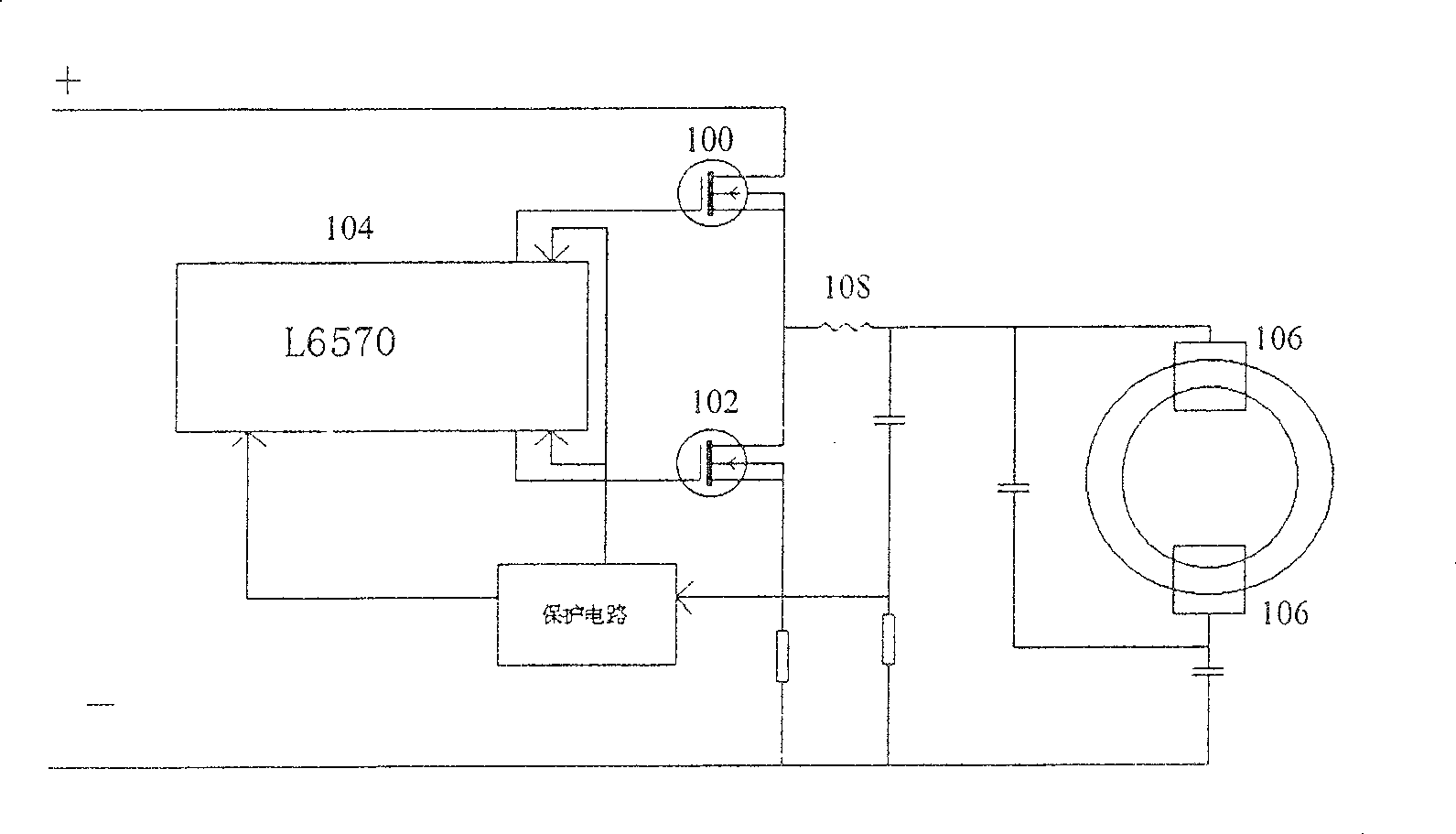
When working, the temperature of the MOS tubes 100 and 102 is high due to the long switching time of the circuit. At the same time, the L6570 is now used as the central processing unit with a single function, no dimming function, and lack of voltage and current for the electromagnetic induction lamp. Sampling monitoring, can not adjust the working state of the electromagnetic induction lamp according to the real-time operation

Method used


Image

  • Dimming circuit for electromagnetic induction lamp
  • Dimming circuit for electromagnetic induction lamp
  • Dimming circuit for electromagnetic induction lamp

Examples


Embodiment Construction

[0030] The technical solutions of the present invention will be further described below in conjunction with the drawings and embodiments.

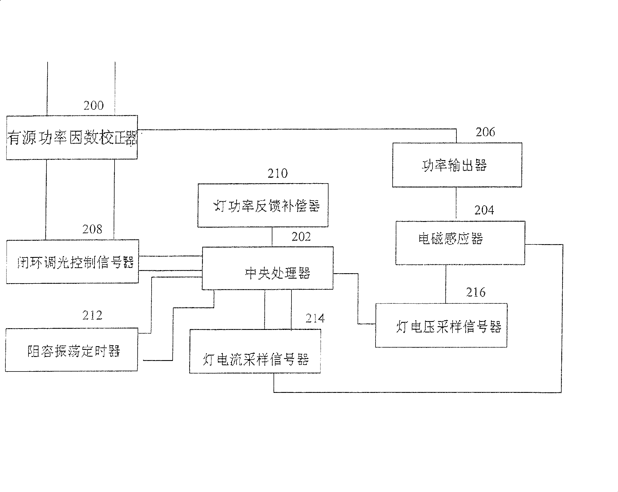
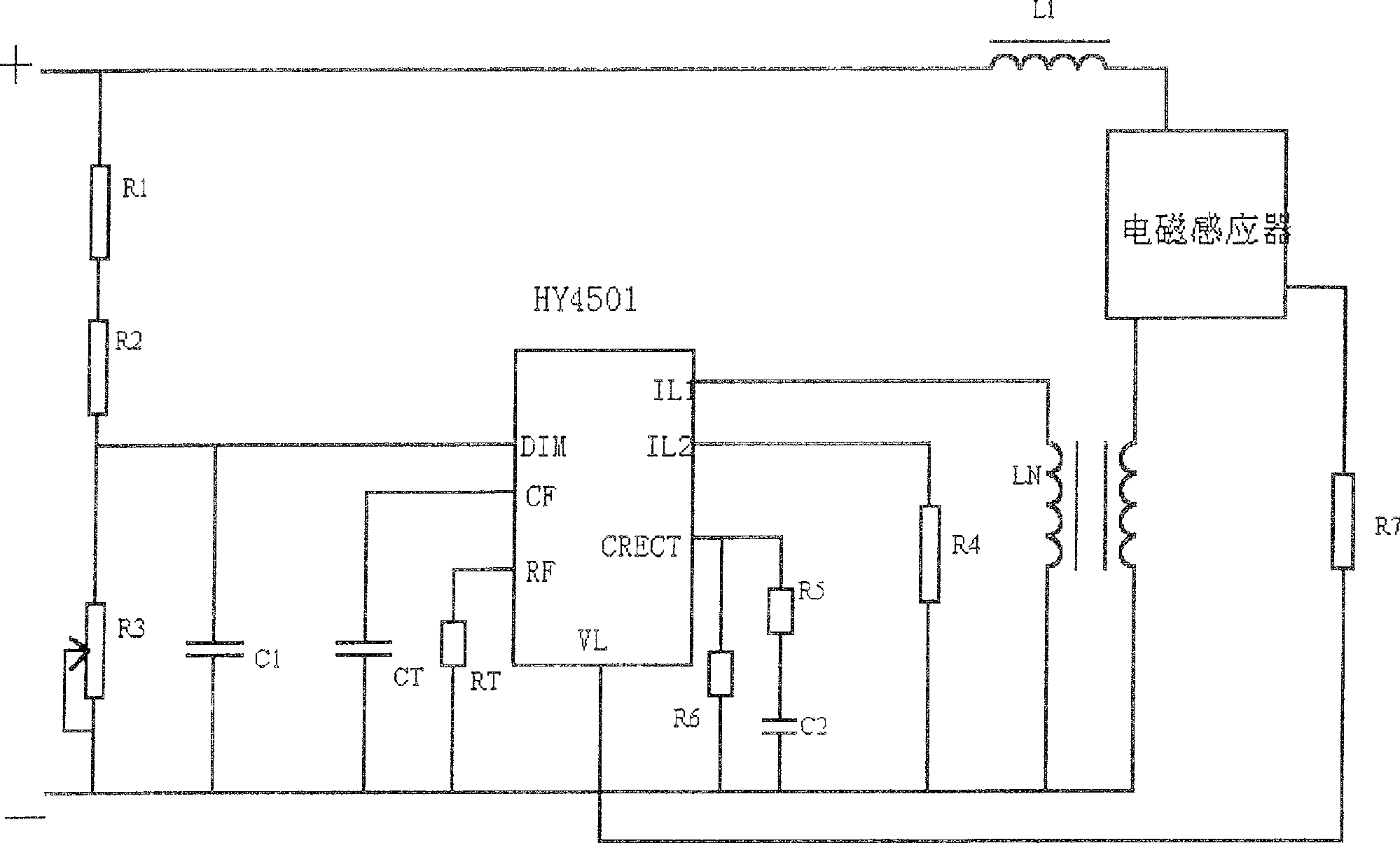
[0031] figure 2 It is a block diagram of a part of the circuit of the electromagnetic induction lamp of the present invention, such as figure 2 As shown, the dimming circuit of the present invention is connected to the electromagnetic induction lamp circuit, and the electromagnetic induction lamp circuit should include an active power factor corrector 200, a central processing unit 202, an electromagnetic inductor 204 and a power output device 206. figure 2 In the illustrated embodiment, the active power factor corrector 200 is connected to a power output device 206, which provides a stable DC voltage for subsequent circuits. The electromagnetic inductor 204 is also connected to the power output device 206, and also connected to the electromagnetic induction lamp tube (not shown in the figure). The power output device 206 is used to p...


PUM


Abstract

The invention discloses a light modulation circuit of an electromagnetic induction lamp which comprises a closed-loop light modulation control signal device, a lamp power feedback compensation device, a resistance-capacitance oscillation timer, a lamp current sampling signalizer and a lamp voltage sampling signalizer. The invention can realize the operation status monitoring and real time adjustment.

Description

technical field [0001] The invention relates to an electromagnetic induction lamp circuit, in particular to a dimming circuit used in an electromagnetic induction lamp circuit. Background technique [0002] Electromagnetic induction lamps are a new generation of energy-saving products with no filament, high luminous efficiency, long life, and high power factor. They can be widely used in homes, factories, offices, roads, engineering construction sites, especially places where lamp tubes are not suitable for replacement. Since the electromagnetic induction lamp is started and ignited without poles, there is no phenomenon that the whole lamp will be scrapped due to the damage of the filament or the exhaustion of the electron powder emission and the blackening of the lamp tube due to the sputtering of the electron powder, and the life of the whole lamp is greatly extended. And the working frequency exceeds 200KHz, which can eliminate the stroboscopic phenomenon. However, the c...

Claims


Application Information

Patent Timeline
Patent Type & Authority Patents(China)
IPC IPC(8): H05B41/392H05B41/28H05B41/282
CPCH05B41/282H05B41/28
Inventor 李维德
Owner SHANGHAI HONGYUAN LIGHTING & ELECTRICAL EQUIP
Why Eureka
Try Eureka