Check patentability & draft patents in minutes with Patsnap Eureka AI!

LED dynamic backlight control circuit

A technology of control circuit and main control circuit, applied in the direction of light source, electric light source, energy-saving control technology, etc., can solve the problem of large power consumption, achieve the effect of improving contrast and ensuring versatility

Inactive Publication Date: 2009-06-03
东莞帝光电子科技实业有限公司
View PDF6 Cites 0 Cited by
  • Summary
  • Abstract
  • Description
  • Claims
  • Application Information

AI Technical Summary

Problems solved by technology

Now the size of liquid crystal display devices is getting bigger and bigger, such as the size of LCD-TV has reached 47 inches, and the increasing power consumption is unacceptable

Method used


Image

  • LED dynamic backlight control circuit
  • LED dynamic backlight control circuit

Examples


Embodiment Construction

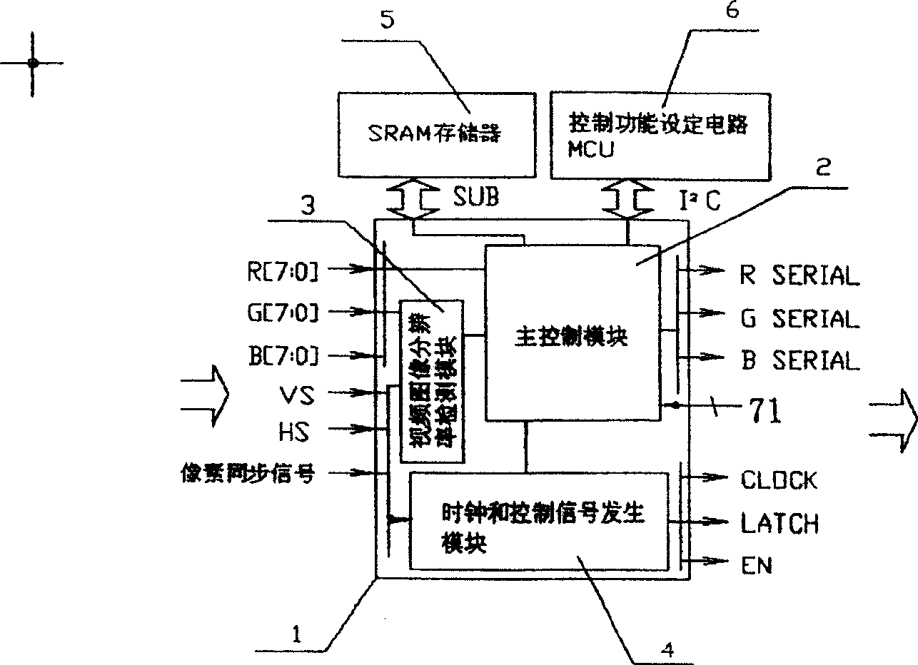
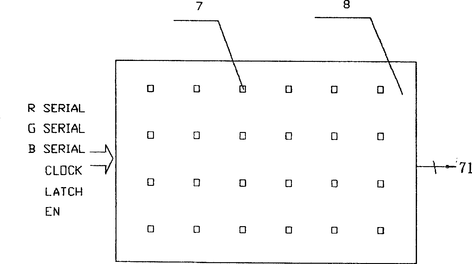
[0017] Such as figure 1 with figure 2 As shown, the present invention provides a LED dynamic backlight control circuit for extracting control data and control signals from the signal provided by the video image processing circuit to drive the LED dynamic backlight, wherein the signal provided by the video image processing circuit includes R , G, B data and pixel clock (PixelClock) signal, vertical synchronization (VS, Vertical Synchronization) signal, horizontal synchronization (HS, Horizontal Synchronization) signal.

[0018] The LED dynamic backlight control circuit of the present invention includes a main control circuit 1, an SRAM memory 5 and a control function setting circuit 6, wherein the main control circuit 1 includes a video image resolution detection module 3, a main control module 2 and a clock and Control signal generation module 4, the main control circuit 1 may be one of MCU, FPGA, DSP, ASIC, SoC or a combination thereof.

[0019] Described video image resol...


PUM


Abstract

The invention relates to a dynamic LED backlight source control circuit. The backlight control circuit comprises a main control circuit including a video image resolution detection module for receiving the R, G, B data and pixel clock signal, field synchronous signal and line synchronous signal to obtain image resolution image; a main control module for receiving the R, G, B data the image resolution data, determining the resolution of the video image and simultaneously obtaining R, G, B tricolor luminous point control data; and a clock and control signal generating module for receiving the pixel clock signal, the field synchronous signal and the line synchronous signal, and generating control signal under control of the main control module. Under control of the control signal produced by the clock and control signal generating module, the main control module transmits the luminous point control data obtained thereby to the dynamic LED backlight source.

Description

technical field [0001] The invention relates to an LED dynamic backlight source control circuit, in particular to a control circuit for a backlight source composed of light-emitting diode (LED) chips. Background technique [0002] Liquid crystal display devices (LCD) are widely used. For liquid crystal display devices (transmissive) that do not emit light themselves, they must rely on the backlight module to provide a light source in order to work normally. In the past, the slightly larger backlight source used CCFL as the light source. CCFL has the advantage of high light efficiency, but it also has the disadvantages of short life, large volume and relatively poor color rendering, especially the brightness of the backlight module made of CCFL cannot be adjusted, and it must be fully loaded when the whole machine is working. bright) work. For a complete machine using LCD as a display device, about 70% of the energy is consumed on the backlight. Now the size of liquid crys...

Claims


Application Information

Patent Timeline
Patent Type & Authority Patents(China)
IPC IPC(8): G09G3/34G09G3/36G09G3/20G09G5/00G09G5/02G02F1/133H05B37/02
CPCY02B20/42Y02B20/40
Inventor 宋义刘冶苏遵惠
Owner 东莞帝光电子科技实业有限公司
Features
  • R&D
  • Intellectual Property
  • Life Sciences
  • Materials
  • Tech Scout
  • Unparalleled Data Quality
  • Higher Quality Content
  • 60% Fewer Hallucinations
Learn More