Electromagnetic fuel injection valve

A fuel injection valve, electromagnetic technology, applied in the direction of fuel injection device, charging system, machine/engine, etc., can solve the problem of poor initial running-in condition of the inner surface of the guide hole, change of fuel flow characteristics, and easy change of sliding surface width, etc. problem, to achieve the effect of good responsiveness, reduced wear and good flow characteristics

Active Publication Date: 2009-06-17
HITACHI ASTEMO LTD
View PDF7 Cites 0 Cited by
  • Summary
  • Abstract
  • Description
  • Claims
  • Application Information

AI Technical Summary

Problems solved by technology

In particular, as described above, if the connecting portion between the inclined surface on the movable iron core side and the sliding surface in the outer surface of the first journal portion is liable to come into contact with the inner surface of the guide hole as the valve assembly inclines, and the inclined surface When the connection with the sliding surface is at an acute angle, the initial run-in with the inner surface of the guide hole is not good, and the amount of wear increases, and the width of the sliding surface is likely to change as the sliding surface wears.
As a result, the responsiveness changes, resulting in a change in the flow characteristics of the fuel
[0006] Therefore, although it is conceivable to simply form the connection portion between the inclined surface and the sliding surface to be curved, in this way, as the sliding surface wears, the angle formed by the connection portion and the sliding surface will also change greatly. thereby greatly affecting the state of friction

Method used


Image

  • Electromagnetic fuel injection valve
  • Electromagnetic fuel injection valve
  • Electromagnetic fuel injection valve

Examples


Embodiment Construction

[0043] Hereinafter, an embodiment of the present invention will be described based on an embodiment of the present invention shown in the drawings.

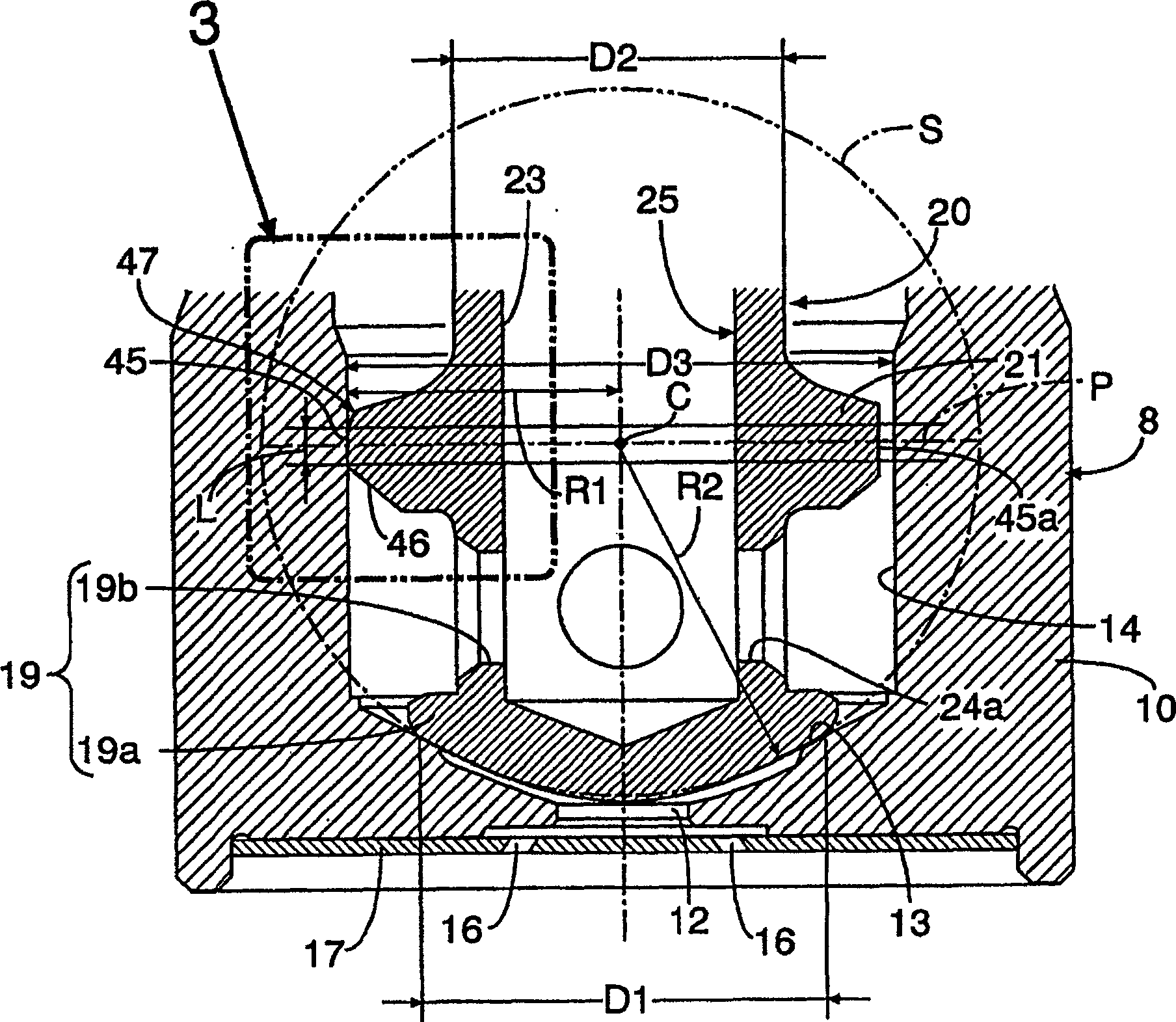
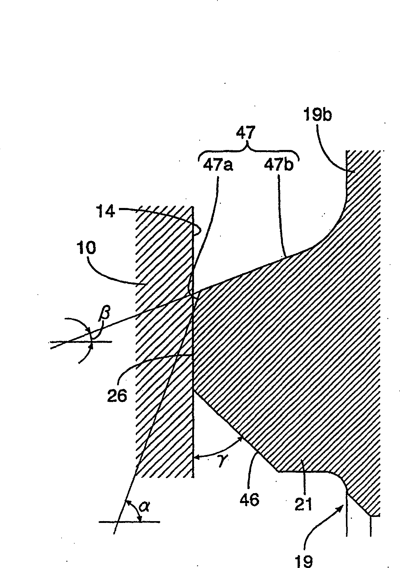
[0044] Figure 1 to Figure 4 One embodiment of the invention is shown.

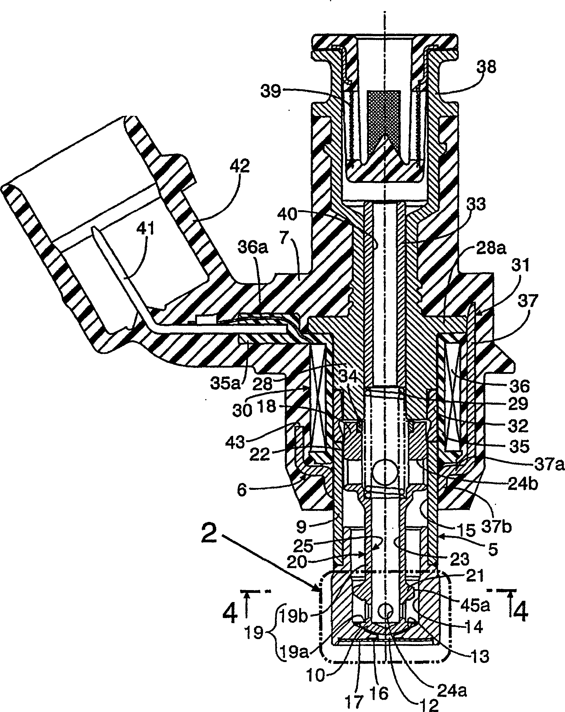
[0045] first,figure 1 Among them, an electromagnetic fuel injection valve for injecting fuel into an unillustrated engine has a valve operating part 5 that accommodates a valve assembly 20 in a valve sleeve 8 having a valve seat 13 at the front end thereof. The valve assembly 20 receives spring force in the direction of seating on the valve seat 13; the solenoid part 6, the solenoid part 6 accommodates the coil assembly 30 in the solenoid sleeve 31 connected to the valve sleeve 8 Inside, the coil assembly 30 can generate electromagnetic force to drive the valve assembly 20 to the side away from the valve seat 13; the covering part 7, the covering part 7 is made of synthetic resin, and integrally has a connection The connecting terminal 41 ... the exposed c...


PUM


Abstract

In an electromagnetic fuel injection valve in which a valve assembly formed by integrally connecting a valve element and a movable core to each other is contained in a valve housing, and a first journal part and a second journal part are provided in the valve assembly so as to be supported slidably in the guide hole in a valve housing, the outside surface of the first journal part (21) is formed by a sliding surface (45) slidable on the inside surface of the guide hole (14) and a pair of tapered tilt surfaces (46, 47) connecting to both the front and rear sides of the sliding surface (45); at least the tilt surface (47) on the movable core side, of both the tilt surfaces (46, 47), is formed of a first tilt surface part (47a) connecting to an end part of the sliding surface (45) and a second tilt surface part (47b) connecting to the first tilt surface part (47a); and an angle that the first tilt surface part (47a) makes with a plane perpendicular to the axis line of a valve shaft part (19b) is set larger than an angle that the second tilt surface part (47b) makes with the plane. Whereby a decrease in initial fitting property and an increase in abrasion loss can be avoided, and the weight of the valve assembly can be reduced while good response and flow characteristic are maintained.

Description

technical field [0001] The invention relates to an electromagnetic fuel injection valve. In the electromagnetic fuel injection valve, a fixed iron core is connected to the rear end of a valve sleeve with a valve seat at the front end; The valve part and the valve shaft part connected with the valve part, the valve core and the movable iron core opposite to the fixed iron core are integrated to form a valve assembly. The spring force on one side of the valve seat is contained in the valve sleeve; the first journal close to the valve seat, and the second journal which is spaced rearward from the first journal along the axial direction The journal is slidably provided on the valve assembly supported by a guide hole provided on the valve sleeve. Background technique [0002] Patent Document 1 discloses an electromagnetic fuel injection valve in which the valve shaft portion in the valve assembly is provided with valve sleeves at intervals in the axial direction. The first and ...

Claims


Application Information

Patent Timeline
Patent Type & Authority Patents(China)
IPC IPC(8): F02M61/12F02M51/06F02M51/08F02M61/18
Inventor 赤羽根明佐藤健一
Owner HITACHI ASTEMO LTD
Why Eureka
Try Eureka