Rolling method for exhaust valve surface

A technology of exhaust valve and valve face, which is applied in the field of rolling, can solve the problems of low hardness of the valve face and short service life, and achieve the effect of extending the overhaul period and improving the service life

Inactive Publication Date: 2009-07-01
HUDONG HEAVY MACHINERY
View PDF4 Cites 0 Cited by
  • Summary
  • Abstract
  • Description
  • Claims
  • Application Information

AI Technical Summary

Problems solved by technology

[0008] The purpose of the present invention is to overcome the shortcomings of low valve surface hardness and short service life caused by the above-mentioned common process for rolling the valve surface of the exhaust valve, and provide a method for rolling the valve surface of the exhaust valve. It is an operation process specially prepared for the hardening of the valve surface of the exhaust valve. It breaks the limitation of the small improvement of the surface hardening hardness of the parts in the past, and greatly improves the hardness of the valve surface of the exhaust valve of the diesel engine, reaching or exceeding the application hardness value.

Method used


Image

  • Rolling method for exhaust valve surface
  • Rolling method for exhaust valve surface

Examples


Embodiment 1

[0030] When the material of the valve surface of the exhaust valve is NiCr18Fe18Nb alloy, the specific steps of the rolling method for the valve surface of the exhaust valve are as follows:

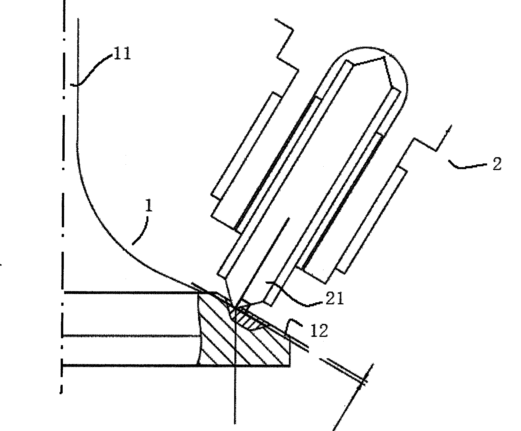
[0031] Fix the exhaust valve on the turntable of the rolling device, and then press the roller near the valve surface of the exhaust valve, and the surface of the roller is coated with molybdenum disulfide as a lubricant;

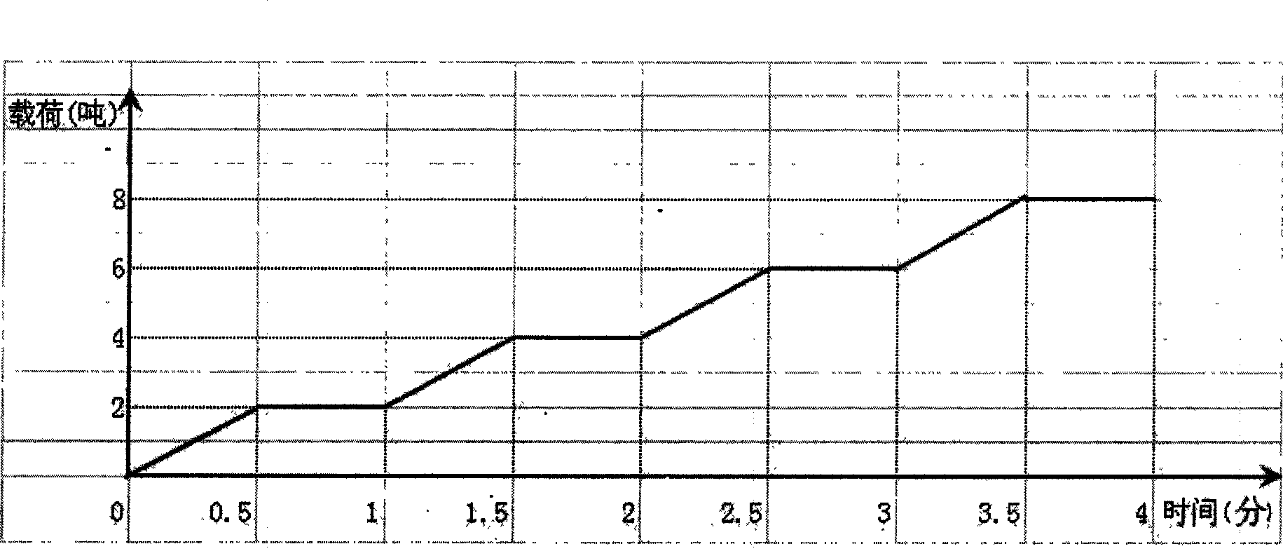
[0032] Align the roller of the rolling device with the inner side of the valve surface, and then apply pressure to the valve surface through the roller. The pressure application process is a fixed pressure within a set period of time, and the pressure increases stepwise with each step. , in this embodiment, the hydraulic system is used to apply pressure to the rollers, and the load is increased by 2 tons every 30 seconds, and the final load is 8 tons. The pressure applied on the valve surface increases from 0 tons to 2 tons; in the second 30 seconds, the hydraulic syst...

Embodiment 2

[0036] When the material of the valve surface of the exhaust valve is NiCr18Co12Nb alloy, the specific steps of the rolling method for the valve surface of the exhaust valve are as follows:

[0037] Fix the exhaust valve on the turntable of the rolling device, and then press the roller near the valve surface of the exhaust valve, and the surface of the roller is coated with tallow as a lubricant;

[0038] Align the roller of the rolling device with the inner side of the valve surface, and then apply pressure to the valve surface through the roller. The pressure application process is a fixed pressure within a set period of time, and the pressure increases stepwise with each step. , in the present embodiment, the hydraulic system is used to apply pressure to the roller, and the load is increased by 2 tons every 30 seconds, and the final load is 10 tons;

[0039] After rolling out the first groove with a depth of 2.2mm on the valve surface, loosen the roller, and then continue t...


PUM

PropertyMeasurementUnit
depthaaaaaaaaaa
hardnessaaaaaaaaaa

Abstract

The invention relates to a method for rolling the valve surface of an exhaust valve. The exhaust valve is fixed on the turntable of the rolling device, and then the roller is pressed on the valve surface of the exhaust valve. Use the rollers to apply pressure to the valve surface. The steps for rolling the rollers to the valve surface are to align the rollers of the rolling device with the inner side of the valve surface, and then press the rollers to the valve surface. Apply pressure, the process of applying pressure is: pressure increase → pressure maintenance → pressure increase → pressure maintenance →...increase to the set maximum pressure, the pressure generally increases in steps, rolling out a certain depth on the valve surface After the first groove, loosen the roller, and then continue to roll out other grooves to the outside of the first groove on the valve surface, and finally process the valve surface that has rolled out multiple grooves to remove the allowance. Using the method of the invention, the surface hardness of the exhaust valve can be increased by 80-110HV compared with the common rolling method, so that the service life of the exhaust valve can be increased by 1-3 times.

Description

technical field [0001] The invention relates to rolling technology, in particular to a method for rolling on the valve surface of an exhaust valve to enhance the hardness of the valve surface. Background technique [0002] In order to improve the service life and safe operation of the exhaust valve of low-speed diesel engine, it is necessary to surfacing hard alloy on the valve surface of the exhaust valve to increase the hardness of the valve surface. However, the required hardness cannot be achieved only after surfacing of cemented carbide, so certain measures are taken to harden the surfacing of cemented carbide. [0003] There are several methods of surface hardening a part, the most common being work hardening. That is, in the cold plastic deformation of the metal, the strength index of the metal, such as the yield point and hardness, is increased, and the plastic index such as the elongation is reduced. Examples of the use of this process are: sandblasting (increasin...

Claims


Application Information

Patent Timeline
Patent Type & Authority Patents(China)
IPC IPC(8): C21D7/04
Inventor 周伟中杜惊霄姚火珍
Owner HUDONG HEAVY MACHINERY
Why Eureka
Try Eureka